Chapter 2
2-23
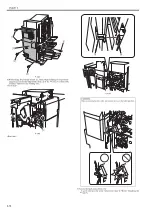
F-2-78
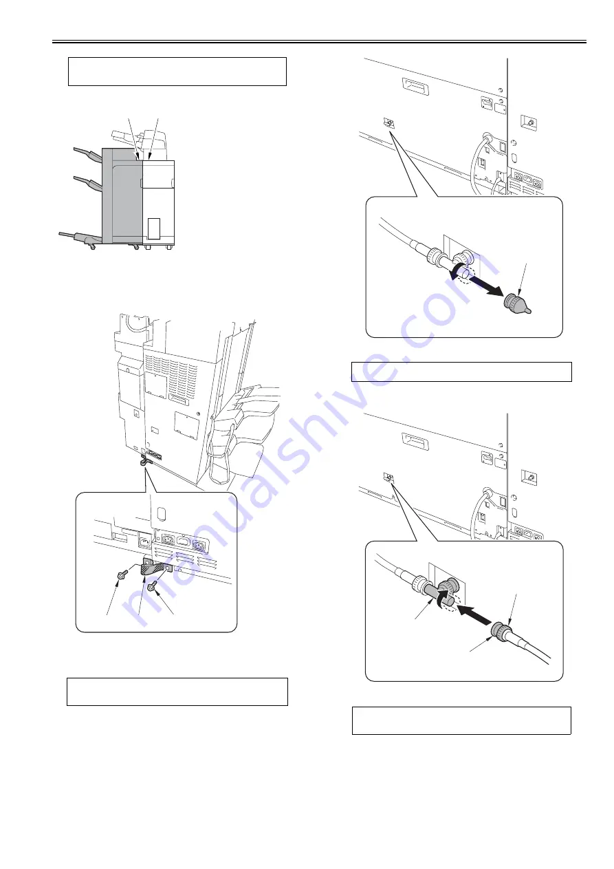
8) Install the rear small cover.
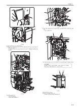
9) Install the shunt cable [1].
- 2 screws (RS tightening; M4X10) [2]
F-2-79
2.3.11 Connecting cable
0021-0960
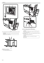
1) Rotate the terminal connector [1] at the back of the host machine in the
direction of the arrow to remove.
F-2-80
2) Connect the ARCNET cable [1] to the terminal at the back of the host ma-
chine, and then rotate the knob [3] in the direction of the arrow to fix.
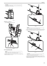
F-2-81
3) Connect the terminal connector [2] and the ARCNET cable [3] to the co-
axial connector [1], and turn their knobs in the direction of the arrows as
shown in the figure to secure.
CAUTION:
Height difference should be /-2mm. Execute "Height Adjustment"
if the difference is +/- 2mm or more.
MEMO:
This item is also variably connected to other option machine, but as an
example, in this case, it is connected to the host machine.
[1]
[2]
[1]
[2]
[2]
MEMO:
Trailing edge connector is not used in the Integration Unit.
CAUTION:
Be sure to turn the knob of the ARCNET cable all the way to connect
otherwise it can cause unstable electrical contact.
[1]
[1]
[3]
[2]
Summary of Contents for Saddle Finisher-AF2
Page 1: ...SERVICE MANUAL Saddle Finisher AF2 MARCH 6 2009...
Page 2: ......
Page 6: ......
Page 12: ...Contents...
Page 13: ...Chapter 1 Specifications...
Page 14: ......
Page 16: ......
Page 22: ......
Page 23: ...Chapter 2 Installation...
Page 24: ......
Page 26: ......
Page 55: ...Chapter 3 Functions...
Page 56: ......
Page 58: ......
Page 104: ...Chapter 3 3 46...
Page 105: ...Chapter 4 Parts Replacement Procedure...
Page 106: ......
Page 110: ......
Page 157: ...Chapter 4 4 47 F 4 213 3 2 1...
Page 158: ......
Page 159: ...Chapter 5 Maintenance...
Page 160: ......
Page 209: ...Chapter 5 5 47 F 5 221 SW382 SW381 SW383 ENTER SW384 SW385 DSP381 1...
Page 218: ......
Page 219: ...Appendix...
Page 220: ......
Page 221: ...General Timing Chart General Circuit Diagram Finisher Sorter DeliveryTray Saddle Finisher AF2...
Page 222: ......
Page 224: ......
Page 225: ...Contents 1 General Circuit Diagram 1 Signal Names 1 General Circuit Diagram 9...
Page 226: ......
Page 243: ......
Page 244: ......


