Chapter 3
3-3
3.3 Stacking Unit
3.3.1 Overview
0020-4687
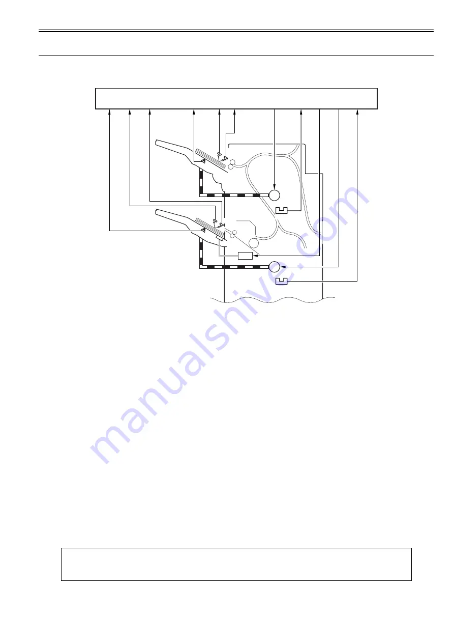
The stacking block moves up and down the 2 delivery trays according to the instructions from the finisher controller PCB.
F-3-5
3.3.2 Tray Ascent/Descent Control
0020-4688
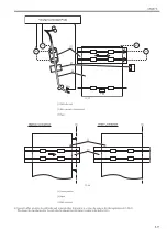
The tray A/B is moved up or down by controlling 2 motors (M22, M23) in response to the instructions from the finisher controller.
The machine uses 2 sensors (PS34, PS35) to check for faults in these motors.
The sensor monitors the rotation of the motors; when any of the following occurs, the finisher controller PCB will stop the drive to the motor and, at the same time,
will communicate the fact to the host machine:
[1] Tray B paper detection signal
[7] Tray A lift motor drive single
[2] Tray B paper surface detection light-emitting signal
[8] Tray A lift motor rotation detection signal
[3] Tray B paper surface detection light-receiving signal
[9] Auxiliary tray solenoid drive signal
[4] Tray A paper detection signal
[10] Tray B lift motor drive signal
[5] Tray A paper surface detection light-emitting signal
[11] Tray B lift motor rotation detection signal
[6] Tray A paper surface detection light-receiving signal
M22: Tray A lift motor
PS35: Tray B lift motor rotation sensor
M23: Tray B lift motor
UN15: Tray A paper side sensor board (emitter)
SL9: Auxiliary tray solenoid
UN16: Train A paper side sensor board (receiver)
PS32: Tray A paper sensor
UN17: Tray B paper side sensor board (emitter)
PS33: Tray B paper sensor
UN18: Train B paper side sensor board (receiver)
PS34: Tray A lift motor rotation sensor
Related Error Code
- E540 (fault in tray A)
While the tray A motor (M22) is rotating, the tray A lift motor rotation detection signal is absent for 250 msec or more.
- E542 (fault in tray A)
While the tray B motor (M23) is rotating, the tray B lift motor rotation detection signal is absent for 250 msec or more.
Finisher controller PCB
UN15
UN17
UN18
UN16
PS34
PS35
PS32
PS33
Tray A
Tray B
[1]
[2]
[3]
[4]
[5]
[6]
[7]
[8]
[9]
[11]
[10]
M22
M23
SL9
Summary of Contents for Saddle Finisher-AF2
Page 1: ...SERVICE MANUAL Saddle Finisher AF2 MARCH 6 2009...
Page 2: ......
Page 6: ......
Page 12: ...Contents...
Page 13: ...Chapter 1 Specifications...
Page 14: ......
Page 16: ......
Page 22: ......
Page 23: ...Chapter 2 Installation...
Page 24: ......
Page 26: ......
Page 55: ...Chapter 3 Functions...
Page 56: ......
Page 58: ......
Page 104: ...Chapter 3 3 46...
Page 105: ...Chapter 4 Parts Replacement Procedure...
Page 106: ......
Page 110: ......
Page 157: ...Chapter 4 4 47 F 4 213 3 2 1...
Page 158: ......
Page 159: ...Chapter 5 Maintenance...
Page 160: ......
Page 209: ...Chapter 5 5 47 F 5 221 SW382 SW381 SW383 ENTER SW384 SW385 DSP381 1...
Page 218: ......
Page 219: ...Appendix...
Page 220: ......
Page 221: ...General Timing Chart General Circuit Diagram Finisher Sorter DeliveryTray Saddle Finisher AF2...
Page 222: ......
Page 224: ......
Page 225: ...Contents 1 General Circuit Diagram 1 Signal Names 1 General Circuit Diagram 9...
Page 226: ......
Page 243: ......
Page 244: ......


