Chapter 3
3-34
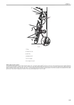
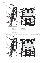
F-3-42
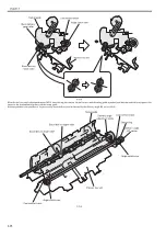
Clearance [A] between the roller guide and the saddle process tray changes in accordance with the position of shutter shift block (hereinafter called as shift block).
The roller guide motor (M104) lifts the shift block. Since the shift block contacts the shutter shift mount at the first time, it moves with the constant clearance [A].
When it continues lifting, it reaches the edge of the shutter shift mount and the clearance [A] is reduced as it moves. In thin paper mode, the machine lifts the shift
block until the clearance [A] becomes the specified degree, and then it lowers the shift block per 5 sheets to enlarge the clearance [A].
A
A
Shutter
shift mount
Shutter
shift block
Slide rack
Gear
Saddle process tray
Roller guide
Summary of Contents for Saddle Finisher-AF2
Page 1: ...SERVICE MANUAL Saddle Finisher AF2 MARCH 6 2009...
Page 2: ......
Page 6: ......
Page 12: ...Contents...
Page 13: ...Chapter 1 Specifications...
Page 14: ......
Page 16: ......
Page 22: ......
Page 23: ...Chapter 2 Installation...
Page 24: ......
Page 26: ......
Page 55: ...Chapter 3 Functions...
Page 56: ......
Page 58: ......
Page 104: ...Chapter 3 3 46...
Page 105: ...Chapter 4 Parts Replacement Procedure...
Page 106: ......
Page 110: ......
Page 157: ...Chapter 4 4 47 F 4 213 3 2 1...
Page 158: ......
Page 159: ...Chapter 5 Maintenance...
Page 160: ......
Page 209: ...Chapter 5 5 47 F 5 221 SW382 SW381 SW383 ENTER SW384 SW385 DSP381 1...
Page 218: ......
Page 219: ...Appendix...
Page 220: ......
Page 221: ...General Timing Chart General Circuit Diagram Finisher Sorter DeliveryTray Saddle Finisher AF2...
Page 222: ......
Page 224: ......
Page 225: ...Contents 1 General Circuit Diagram 1 Signal Names 1 General Circuit Diagram 9...
Page 226: ......
Page 243: ......
Page 244: ......


