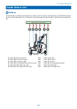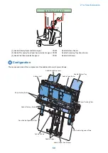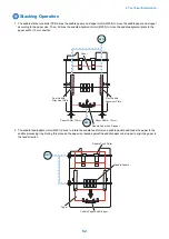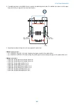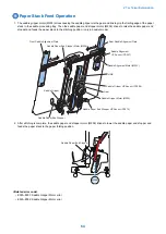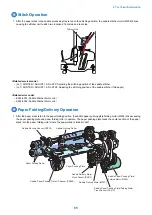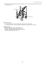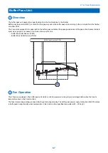
Power Supply
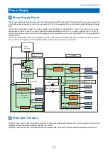
Power Supply Route
The 24V are supplied to the buffer pass controller PCB through the buffer pass relay PCB and the buffer pass power supply PCB
in the buffer pass unit when the host machine is turned ON. The 24V is supplied from the buffer pass unit to the finisher controller
PCB.
The 24V is converted into 5V and 3.3V by the regulator IC on the finisher controller PCB. The 24V is used to drive the motors
and clutches and fan and the 5V is used to drive the sensors and switches and the 3.3V is used to drive the logic. The 24V is
shut down when the opening of the front cover or swing guide is detected by the front cover switch (SW101) or swing guide safety
switch (SW102).
The 24V is converted into 5VDC by the regulator IC on the saddle stitcher controller PCB to drive sensors. It is also converted
into 3.3VDC by the regulator IC on the saddle stitcher controller PCB to drive ICs on the PCB.
Sensors/Switches
Regulator IC
3.3V
Logic
Swing Guide Safety Switch
(SW102)
Front Cover Switch
(SW101)
24V
Motors
24V
Clutches
24V
Fan
Regulator IC
5V
Finisher Controller PCB
Regulator IC
3.3V
Logic
5V
Sensor
24V
Motor
Driver IC
5V
Puncher Unit
Motors
24V
Saddle Stitcher Controller PCB
Motor
Driver IC
Buffer Pass
Controller PCB
3.3V
3.3V
24V
Sensors
Logic
Motor Driver IC
Motors
Fans
24V
Regulator IC
Relay signal
Buffer Pass
Relay PCB
Buffer Pass Power
Supply PCB
Host
Machine
AC
AC
24V
24V
Buffer Pass
Unit
Finisher
Remote signal
Protection Function
The 24V circuits (used to drive the motors and clutches and fan) are provided with the fuses or the motor drivers with an overcurrent
protective function to provide protection from the over current.
The power input circuit of each controller PCB is also provided with a fuse which is blown when an excessive current flows.
2. Technical Explanation
73
Summary of Contents for Staple Finisher-AA1
Page 1: ...Revision 4 0 Staple Finisher AA1 Booklet Finisher AA1 Service Manual ...
Page 12: ...Product Overview 1 Features 5 Specifications 6 Names of Parts 14 Optional Configuration 20 ...
Page 83: ...Periodical Service 3 Periodic Servicing Tasks 76 ...
Page 87: ...3 Remove the 2 Connectors 1 2x 1 4 Parts Replacement and Cleaning 79 ...
Page 89: ...Main Units Parts 4 5 6 7 8 1 2 3 4 Parts Replacement and Cleaning 81 ...
Page 128: ...4x 1 2 2 3 3 2x 4 Parts Replacement and Cleaning 120 ...
Page 150: ...Adjustment 5 Overview 143 Basic Adjustment 148 Adjustments When Replacing Parts 173 Other 184 ...
Page 193: ...Troubleshooting 6 Making Initial Checks 186 Processing Tray Area 187 Saddle Stitcher Area 188 ...
Page 204: ...4 5 6 7 8 9 7 Installation 196 ...
Page 205: ...10 7 Installation 197 ...
Page 223: ...2 3 2x 7 Installation 215 ...
Page 224: ...APPENDICES Service Tools 217 General Circuit Diagram 218 ...

