[2]
[2]
[1]
[1]
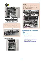
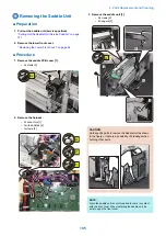
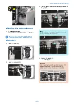
CAUTION:
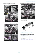
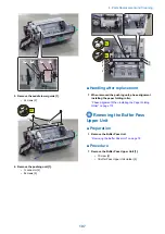
Point to Note When Installing the Paddle
• Insert the claw of the paddle [1] into the groove [2].
• Align the paddle end face [3] with the shaft end
face [4].
[1]
[1]
[2]
[1]
[4]
[3]
[1]
[2]
[4]
[3]
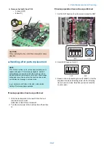
■ Handling after parts replacement
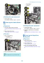
1. Clear the parts counter.
(LV1) COPIER > COUNTER > DRBL-2 > FIN-MPDL
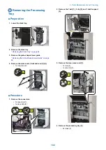
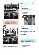
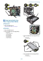
Removing the Lower Stack
Delivery Roller Clutch (CL102)
■ Preparation
1. Remove the rear cover.
“ Removing the Rear Cover” on page 94
■ Procedure
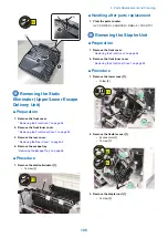
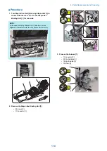
1. Remove the clutch [1].
• 1 connector [2]
• 1 clip [3]
[1]
[2]
[3]
1x
■ Handling after parts replacement
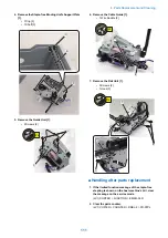
1. Clear the parts counter.
(LV1) COPIER > COUNTER > DRBL-2 > SW-RL-CL
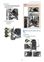
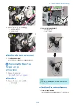
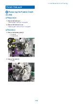
Removing the Escape Feed
Clutch (CL101)
■ Preparation
1. Remove the rear cover.
“ Removing the Rear Cover” on page 94
2. Remove the puncher unit.
NOTE:
Only when the puncher unit is installed, refer the
installation procedure to remove the puncher unit.
■ Procedure
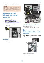
1. Remove the support plate [1].
• 1 screw [2]
4. Parts Replacement and Cleaning
114
Summary of Contents for Staple Finisher-AA1
Page 1: ...Revision 4 0 Staple Finisher AA1 Booklet Finisher AA1 Service Manual ...
Page 12: ...Product Overview 1 Features 5 Specifications 6 Names of Parts 14 Optional Configuration 20 ...
Page 83: ...Periodical Service 3 Periodic Servicing Tasks 76 ...
Page 87: ...3 Remove the 2 Connectors 1 2x 1 4 Parts Replacement and Cleaning 79 ...
Page 89: ...Main Units Parts 4 5 6 7 8 1 2 3 4 Parts Replacement and Cleaning 81 ...
Page 128: ...4x 1 2 2 3 3 2x 4 Parts Replacement and Cleaning 120 ...
Page 150: ...Adjustment 5 Overview 143 Basic Adjustment 148 Adjustments When Replacing Parts 173 Other 184 ...
Page 193: ...Troubleshooting 6 Making Initial Checks 186 Processing Tray Area 187 Saddle Stitcher Area 188 ...
Page 204: ...4 5 6 7 8 9 7 Installation 196 ...
Page 205: ...10 7 Installation 197 ...
Page 223: ...2 3 2x 7 Installation 215 ...
Page 224: ...APPENDICES Service Tools 217 General Circuit Diagram 218 ...


