background image

Switches 

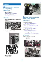
 Removing the Front Cover

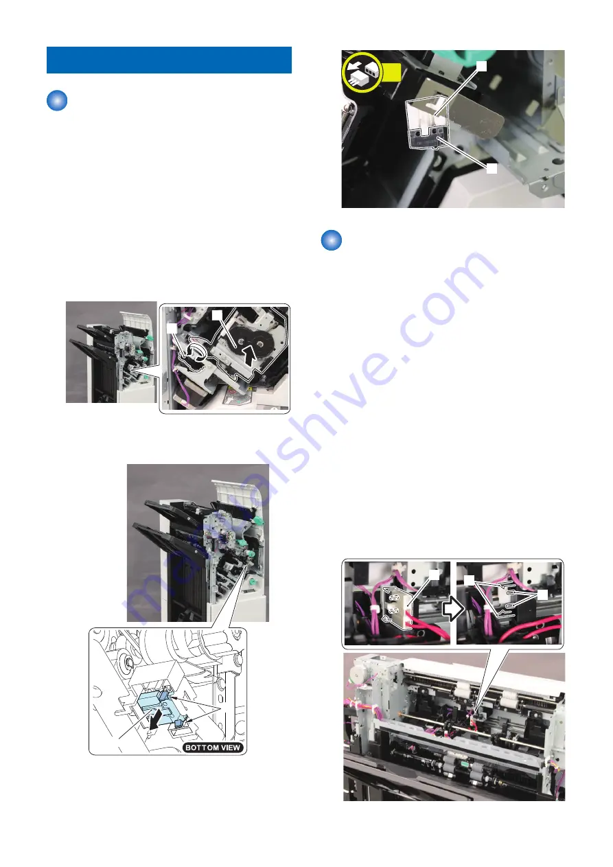
Switch (SW101)

■ Preparation

1. Remove the front cover.

“ Removing the Front Cover” on page 94

2. Remove the front inner cover.

“ Removing the Front Inner Cover” on page 95

■ Procedure

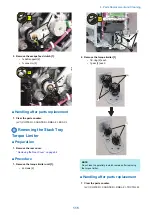
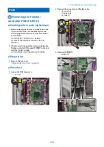
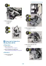
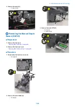
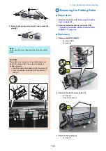
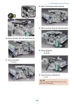
1. Turn the Dial[2] and then move the Stapler Unit[1] in

about 10cm.

[2]

[1]

2. Remove the switch assembly [1].

• 2 claws [2]

[2]

[1]

3. Remove the switch [1].

• 1 connector [2]

[1]

[2]

1x

 Removing the Swing Guide

Safety Switch (SW102)

■ Preparation

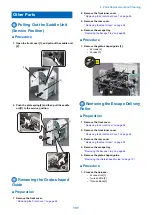
1. Remove the front cover.

“ Removing the Front Cover” on page 94

2. Remove the front inner cover.

“ Removing the Front Inner Cover” on page 95

3. Remove the rear cover.

“ Removing the Rear Cover” on page 94

4. Remove the escape tray.

“Removing the Escape Tray” on page 96

5. Remove the grate-shaped guide

“Removing the Grate-shaped Guide” on page 131

■ Procedure

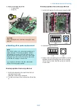
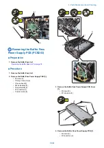
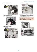
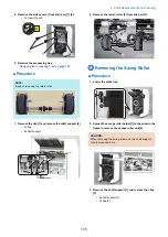
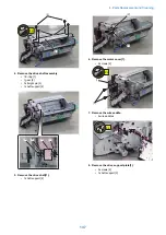
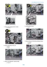
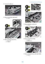
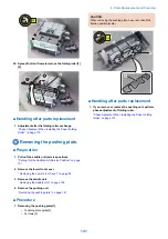
1. Remove the switch assembly [1].

• 2 claws [2]
• 2 bosses [3]

[3]

[2]

[1]

4. Parts Replacement and Cleaning

129

Summary of Contents for Staple Finisher-AA1

Page 1: ...Revision 4 0 Staple Finisher AA1 Booklet Finisher AA1 Service Manual ...

Page 2: ...g or short period Canon will issue a new edition of this manual The following paragraph does not apply to any countries where such provisions are inconsistent with local law Trademarks The product names and company names used in this manual are the registered trademarks of the individual companies Copyright This manual is copyrighted with all rights reserved Under the copyright laws this manual ma...

Page 3: ... door and closing the delivery unit door which results in supplying the machine with power 2 In the digital circuits 1 is used to indicate that the voltage level of a given signal is High while 0 is used to indicate Low The voltage value however differs from circuit to circuit In addition the asterisk as in DRMD indicates that the DRMD signal goes on when 0 In practically all cases the internal me...

Page 4: ...xternal View Front 14 External View Rear 15 External View Internal 17 Cross Section 18 Optional Configuration 20 2 Technical Explanation 21 Basic Configuration 22 Component Configuration 22 Overview of the Electrical Circuitry 23 Controls 25 Controls 25 Basic Operation 26 Outline 26 Feeding Unit 31 Outline 31 Basic Operation 32 Feed switch operation 33 Shift Operation 34 Buffer Operation 37 Stack ...

Page 5: ... Supply Route 73 Protection Function 73 Upgrading 74 3 Periodical Service 75 Periodic Servicing Tasks 76 4 Parts Replacement and Cleaning 77 Removing this Machine 78 Removing the Finisher 78 Removing the Buffer Pass Unit 78 List of Parts 80 External Internal Covers 80 Main Units Parts 81 List of Clutches 84 List of Motors 84 List of Sensors 87 List of Switches Fans 89 List of PCBs 91 Other Parts 9...

Page 6: ...B201 118 Removing the Buffer Pass Controller PCB PCB201 118 Removing the Buffer Pass Power Supply PCB PCB203 119 Sensor 121 Removing the Delivery Sensor PS102 121 Clutch Solenoid 122 Removing the Paddle Clutch CL103 122 Motors 123 Removing the Front Alignment Motor M107 123 Removing the Rear Alignment Motor M108 123 Removing the Tray Auxiliary Guide Motor M109 124 Removing the Paper End Assist Mot...

Page 7: ...4 6 Troubleshooting 185 Making Initial Checks 186 List of Initial Check Items 186 Processing Tray Area 187 Adjusting the Alignment and the Staple Position 187 Saddle Stitcher Area 188 Fold Placement Saddle Stitch Adjustment 188 7 Installation 189 How to Utilize This Installation Procedure 190 Illustrations Used in This Procedure 190 Product Name 190 Checking Before Installation 191 Checking the In...

Page 8: ...s After Completion of Adjustments 212 Making Checks After Completion of Installation Work 213 Disposal Parts Check 213 Operation Check 213 Detaching from the Host Machine 214 Finisher 214 Buffer Pass Unit 214 APPENDICES 216 Service Tools 217 Solvents and Oils 217 Special Tools 217 General Circuit Diagram 218 General Circuit Diagram 1 3 218 General Circuit Diagram 2 3 219 General Circuit Diagram 3 ...

Page 9: ...Safety Precautions Notes Before Servicing 2 Points to Note at Cleaning 2 Notes On Assembly Disassembly 2 ...

Page 10: ... conduction binding screws with washers are used to attach the grounding wire and the varistor Ensure to use the right screw type when assembling 5 Unless it is specially needed do not operate the device with some parts removed 6 Never remove the paint locked screws when disassembling 7 During disassembly reassembly or transportation of the printer remove the cartridge if required When the cartrid...

Page 11: ...Resin Metal Resin Tightening torque N m M4 Approx 1 6 Approx 1 6 Approx 1 6 Approx 0 8 Approx 1 6 Approx 0 8 Approx 1 6 Approx 0 8 M3 Approx 0 8 Approx 0 8 Approx 0 6 Approx 0 6 Approx 0 6 Approx 0 6 Approx 0 6 Approx 0 6 For PCB refer to the tightening torque value of resin fastened member RS tight Type of Screws W Sems Binding TP Safety Precautions 3 ...

Page 12: ...Product Overview 1 Features 5 Specifications 6 Names of Parts 14 Optional Configuration 20 ...

Page 13: ...e stack tray and the upper lower escape trays Staple manual staple and staple free binding functions are integrated allowing versatile stapling that suit the various demands Basic performance is substantial That is the high capacity stacking function that can stack up to 3 250 sheets escape tray 250 sheets stack tray 3 000 sheets the staple function that can staple up to 50 sheets and booklet bind...

Page 14: ...STMTR EXEC SRA3 12 18 8K 16K 16KR Shift sort mode Escape tray A3 A4 B4 B5 11 17 LTR EXEC 8K 16K Stack tray A3 A4 A4R B4 B5 11 17 LGL LTR LTRR EXEC 8K 16K Staple mode Stack tray A3 A4 11 17 LGL LTR LTRR EXEC 8K 16K Staple free binding mode Stack tray A3 A4 11 17 LTR 8K 16K Stacking capacity without folding sheets Processing tray Feed length 182 mm to 215 9 mm 50 sheets or less Feed length More than...

Page 15: ...eets The stacking capacity for paper weighing 59 g m2 or less is for up to the large size height Mixed stacking ca pacity without folding sheets Escape tray Mixed size Plain paper combination of A4 B5 and LTR only Height 47 mm 3 mm or less Combinations of other paper sizes Height 24 mm 3 mm or less The stacking capaci ties are estimates when converting weight to number of 81 4 g m2 sheets Stacking...

Page 16: ...size 5 5 mm or less 52 to 90 g m2 50 sheets 30 sheets More than 90 to 105 g m2 30 sheets 20 sheets More than 105 to 300 g m2 2 sheets 2 sheets Manual stapling Paper thickness 6 5mm or less Equivalent to 50 sheets or less 1 point stapling Converting weight to number of 64 g m2 sheet Staple supply Special staple cartridge 5 000 staples Staple detection Available Initial feed of staple Available Pape...

Page 17: ... EXEC 8K 16 K 5 0 2 0 mm 5 0 2 0 mm Front 1 point stapling 30 deg A4R LGL LTRR 4 0 2 0 mm 5 0 2 0 mm Rear 1 point stapling 45 deg A3 A4 B4 B5 11 17 LTR EXEC 8K 16K 5 0 2 0 mm 5 0 2 0 mm Rear 1 point stapling 30 deg A4R LGL LTRR 4 0 2 0 mm 5 0 2 0 mm 1 Product Overview 9 ...

Page 18: ... 0 2 0 mm 120 mm 8K 16K 69 5 4 0 mm 189 5 4 0 mm 5 0 2 0 mm 120 mm Manual stapling 5 0 2 0 mm 5 0 2 0 mm Staple Free Binding Unit Item Specifications Remarks Binding method Pressing by rotating cam Binding position Rear 1 point binding Tooth shaped Bindable size A3 A4 11 17 LTR 8K 16 K Binding capacity 52 to 64 g m2 5 sheets or less More than 64 to 81 4 g m2 4 sheets or less More than 81 4 to 105 ...

Page 19: ... body page Capacity Without stitch 52 to 105 g m2 1 to 3 sheets More than 105 to 256 g m2 1 sheet With stitch 52 to 81 4 g m2 2 to 20 sheets More than 81 4 to 105 g m2 2 to 10 sheets More than 105 to 150 g m2 2 to 5 sheets More than 150 to 209 g m2 2 to 4 sheets More than 209 to 220 g m2 2 or 3 sheets Includes one cover page Stackable pa per Thin plain recycled environmental heavy coated paper Sta...

Page 20: ... Item Description Remarks Placement Center Installation Build in type Stacking size Buffer pass delivery tray Feed direction 139 7 to 457 0mm Width direction 100 0 to 305 0mm Long original pa per 630mm 1200mm is availa ble to fed if jam is not occurred Stacking capacity Buffer pass delivery tray Height 15mm or less equivalent of 100 sheets Transparency Tracing Paper and Labels are 20 sheets or les...

Page 21: ...available Control panel Available manual staple button Dimensions 537 mm 637 mm W 969 mm 1 016 mm H 623 mm D When the auxiliary tray is pulled out Weight Staple finisher about 30 kg Booklet finisher about 53kg Power supply Supplied from the buffer pass unit DC 24 5V Power consumption 192W or less when puncher unit is installed 1 Product Overview 13 ...

Page 22: ...8 9 No Part Name No Part Name 1 Upper Cover Unit 6 Caster Cover Front 2 Manual Staple Button 7 Caster Cover Rear 3 Front Cover 8 Stack Tray 4 Manual Staple Paper Inlet Slit 9 Escape Tray 5 Lower Front Cover Booklet Finisher 10 1 2 3 4 5 6 7 8 9 1 Product Overview 14 ...

Page 23: ... Front Cover 8 Saddle Delivery Tray 4 Manual Staple Paper Inlet Slit 9 Stack Tray 5 Lower Front Cover 10 Escape Tray Buffer Pass Unit 1 2 No Part Name No Part Name 1 Buffer Pass Delivery Tray 2 Buffer Pass Feed Outlet Port External View Rear Staple Finisher 1 No Part Name 1 Rear Cover 1 Product Overview 15 ...

Page 24: ... Booklet Finisher 1 No Part Name 1 Rear Cover Buffer Pass Unit 1 No Part Name 1 Buffer Pass Feed Inlet Port 1 Product Overview 16 ...

Page 25: ...External View Internal Staple Finisher 1 No Part Name 1 Front Inner Cover Booklet Finisher 1 2 No Part Name No Part Name 1 Front Inner Cover 2 Saddle Unit 1 Product Overview 17 ...

Page 26: ...e No Part Name 1 Escape Delivery Roller 8 Escape Feed Roller 1 2 Escape Tray 9 Pre Processing Roller 3 Upper Stack Delivery Roller 10 Buffer Saddle Inlet Flapper 4 Lower Stack Delivery Roller 11 Escape Inlet Flapper 5 Stack Tray 12 Inlet Roller 6 Alignment Plate 13 Buffer Saddle Inlet Roller 7 Stapler Unit 1 Product Overview 18 ...

Page 27: ...ck Delivery Roller 14 Escape Inlet Flapper 5 Stack Tray 15 Inlet Roller 6 Alignment Plate 16 Buffer Saddle Inlet Roller 7 Stitcher Unit 17 Stapler Unit 8 Paper Folding Roller 18 Saddle Feed Roller 9 Saddle Delivery Roller 19 Paper Pushing Plate 10 Saddle Delivery Tray Buffer Pass Unit 1 4 3 2 No Part Name No Part Name 1 Buffer Pass Feed Roller 1 3 Buffer Pass Feed Roller 3 2 Buffer Pass Feed Rolle...

Page 28: ...Optional Configuration This equipment can incorporate a puncher unit option Buffer Pass Unit Puncher Unit Puncher Unit Booklet Finisher Staple Finisher 1 Product Overview 20 ...

Page 29: ...ation 2 Basic Configuration 22 Controls 25 Basic Operation 26 Feeding Unit 31 Stack Escape Tray Unit 40 Processing Tray Unit 46 Saddle Stitcher Unit 59 Buffer Pass Unit 67 Jam Detection 69 Power Supply 73 Upgrading 74 ...

Page 30: ... 5 major blocks Buffer Pass Unit Feed Unit Processing Unit Stack Tray Unit and Saddle Stitcher Unit Staple Finisher Tray Unit Feed Unit Processing Tray Unit Buffer Pass Unit Booklet Finisher Tray Unit Feed Unit Processing Tray Unit Saddle Stitcher Unit Buffer Pass Unit 2 Technical Explanation 22 ...

Page 31: ...taple Finisher Finisher Controller PCB Host Machine Motor Fan Clutch Sensor Switch Puncher Controller PCB CPU Motor Driver Buffer Pass Controller PCB UFDI Communication Serial Communication UFDI Communication Related service mode Lv 1 COPIER DISPLAY VERSION SORTER Related error code E503 0041 Error in communication between the Finisher and Buffer Pass E503 0042 Error in communication between the F...

Page 32: ...ler PCB Buffer Pass Unit The buffer pass operation sequence is controlled by the buffer pass controller PCB The buffer pass controller PCB has a 32 bit CPU that performs sequence control The buffer pass controller PCB receives various commands through the communication cable from its host to drive the motors It also sends sensor information to its host through the communication cable Finisher Cont...

Page 33: ...gnment Shifting Operation Alignment Shifting Operation on page 50 Staple Operation Staple Operation on page 52 Staple free Binding Operation Staple free Binding Operation on page 55 Stack Delivery Operation Stack Delivery Operation on page 58 Saddle Stitcher Unit Outline Outline on page 59 Configuration Configuration on page 60 Basic Operation Basic Operation on page 61 Stacking Operation Stacking...

Page 34: ...per Stack Delivery Roller Pre Processing Roller 2 The paper delivered by the pre processing roller is stacked on the processing tray by the paper end pushing guide and paddle The return roller and processing tray stopper align paper in the feed direction Return Roller Processing Tray Stopper Paddle Paper End Pushing Guide 3 The alignment plates are used to align paper in the width direction Rear A...

Page 35: ...nly in staple mode or staple free binding mode Stapler Unit Staple Free Binding Unit 6 After being shifted the paper stack on the processing tray that has been stacked by the paper end assist guide and stack delivery roller are delivered to the stack tray Upper Stack Delivery Roller Paper End Assist Guide Lower Stack Delivery Roller 2 Technical Explanation 27 ...

Page 36: ...he paper delivered to the escape delivery roller is shifted only during shift sort mode and delivered to the escape tray Escape Delivery Roller Paper During saddle stitcher unit and buffer path unit feeding 1 The paper delivered from the host machine is fed by the inlet roller pre processing roller and stack delivery roller Inlet Roller Lower Stack Delivery Roller Upper Stack Delivery Roller Pre P...

Page 37: ...g saddle delivery tray delivery 1 The paper fed to the saddle stitcher unit is then stacked on the saddle processing tray by the saddle feed roller and saddle paddle Saddle Feed Roller Saddle Paddle 2 The saddle alignment plates are used to align paper in the width direction Rear Saddle Alignment Plate Front Saddle Alignment Plate Paper 3 The operations described in steps 1 and 2 are repeated for ...

Page 38: ... Saddle Gripper 5 After the paper is folded by the paper pushing plate and paper folding roller it is delivered on to the saddle delivery tray by the saddle delivery roller Paper Folding Roller Paper Pushing Plate Saddle Delivery Roller Saddle Delivery Tray 2 Technical Explanation 30 ...

Page 39: ...Clutch drive signal CL103 Paddle Clutch 4 Escape Delivery Shift Motor drive signal M106 Escape Delivery Shift Motor 5 Escape Feed Clutch drive signal CL101 Escape Feed Clutch 6 Inlet Feed Motor drive signal M101 Inlet Feed Motor 7 Flapper Motor drive signal M104 Flapper Motor 8 Pre processing Buffer Motor drive signal M102 Pre processing Buffer Motor Finisher Controller PCB PS114 PS111 PS101 PS103...

Page 40: ...ift operation When paper is stacked in the escape tray switch the paper position for each job only when shift sort mode is selected 3 Buffer operation A specified number of sheets are stored in the buffer path unit and fed with the paper received from the host machine to the processing tray unit Flow of Paper 3 1 2 To Escape Tray To Processing Tray To Stack Tray To Saddle Stitcher Unit From Connec...

Page 41: ...The home position is detected by the flapper HP sensor PS105 The flappers are driven by motor flapper motor M104 Link Buffer Saddle Inlet Flapper Inlet Sensor PS101 Escape Inlet Flapper Link Flapper Motor M104 Cam Flapper HP Sensor PS105 Paper feed to the stack tray processing tray Escape Inlet Flapper OFF Buffer Saddle Inlet Flapper OFF Flapper HP Sensor PS105 OFF Flapper HP Sensor PS105 Buffer S...

Page 42: ...am Flapper HP Sensor PS105 Buffer Saddle Inlet Flapper Shift Operation This equipment delivers paper fed to the escape tray unit to the escape tray by shifting the escape delivery roller to the front and back The escape delivery roller is shifted by the escape delivery shift motor M106 The home position is detected by the escape delivery roller HP sensor PS112 Escape Delivery Shift Motor M106 Rack...

Page 43: ...d from the center reference po sition Paper width 290 mm to 297 mm Paper length 182 mm to 431 8 mm Front shift position 25mm front ward from the center reference po sition Rear shift position 25mm front ward from the center reference po sition The following paper does not do shift operation Paper width less than 220mm or more than 297mm Paper length less than 182mm or more than 431 8mm Shift Opera...

Page 44: ... When the paper width is 220 mm to 290 mm and paper length is 182 mm to 431 8 mm Front shift 30mm Paper Escape Delivery Roller Rear shift 30mm Paper Escape Delivery Roller 2 Technical Explanation 36 ...

Page 45: ...ing tray unit as a paper stack This allows paper to be fed without sacrificing print processing speed In addition the buffer operation is not performed at the staple free binding mode Buffer operation condition Weight of paper that can be buffered 60 to 105 g m2 Paper size paper length 182 mm to 220 mm paper width 216 1mm to 297mm Number of sheets that can be buffered 1 to 3 sheets Up to 2 sheets ...

Page 46: ...1 Buffer Sensor PS103 2 The flapper motor M104 is driven to switch the buffer saddle inlet flapper The pre processing buffer motor M102 is driven in reverse to feed the paper to the buffer path unit The paper trailing edge is detected by the buffer sensor PS103 and the paper is fed a specified amount where it stops M102 M104 Buffer Saddle Inlet Flapper Cam Flapper HP Sensor PS105 Inlet Sensor PS10...

Page 47: ...PS105 Inlet Sensor PS101 Buffer Sensor PS103 Related service mode Lv 1 SORTER ADJUST BFF SFT Adjusting the displacement amount of the buffered paper 1st to 2nd sheets Lv 1 SORTER ADJUST BFF SFT2 Adjusting the displacement amount of the buffered paper 2nd to 3rd sheets Lv 1 SORTER ADJUST NST SPD Adjusting the delivery speed at the non sort mode Lv 1 SORTER ADJUST ESC1 SPD Adjusting the delivery spe...

Page 48: ...it has a sensor for detecting the paper surface of the stack tray unit five sensors for detecting whether the paper delivered in the tray is full and two sensors for detecting the position of the stack tray Escape Tray Stack Tray Escape Tray Full Sensor PS113 Stack Tray Upper Limit Sensor PS110 Stack Tray HP Sensor PS106 Stack Tray Full Sensor 1 PS107 Stack Tray Full Sensor 2 PS108 Stack Tray Full...

Page 49: ...home position of the stack tray The stack tray upper limit sensor PS110 detects the upper limit position of the stack tray Stack Tray Stack Tray Full Sensor 3 PS109 Stack Tray Drive Belt Stack Tray Torque Limiter Stack Tray Shift Motor M105 Stack Tray Full Sensor 2 PS108 Stack Tray Full Sensor 1 PS107 Stack Tray HP Sensor PS106 Stack Tray Upper Limit Sensor PS110 2 Technical Explanation 41 ...

Page 50: ...Tray Stack Tray Paper Surface Sensor Upper light receiving PBA102 Stack Tray Paper Surface Sensor Lower light receiving PBA103 Stack Tray Upper Limit Sensor PS110 Stack Tray HP Sensor PS106 PBA103 PBA102 Stack Tray PS106 Paper absence near empty condition When the paper stacked in the stack tray increases the LED light from the stack tray paper surface sensor light emitting PBA101 is blocked When ...

Page 51: ...not executed in the following conditions This is to reduce the sound of tray movement From power on until the initial operation starts When an error or jam occurs When in sleep mode When the tray function is restricted If the stack tray full sensors 1 2 and 3 PS107 PS108 and PS109 are on when the LED light from the stack tray paper surface sensor light emitting PBA101 is blocked the stack tray pap...

Page 52: ... Sensor name Role Stack Tray Full Sensor 1 PS107 Paper full detection of large size coated paper Stack Tray Full Sensor 2 PS108 Paper full detection of large size plain paper Paper full detection of small size coated paper Stack Tray Full Sensor 3 PS109 Paper full detection of small size plain paper Small size feed length 220 mm or less large size feed length more than 220 mm 2 Technical Explanati...

Page 53: ...Flag Escape Tray Escape Tray Full Sensor PS113 NOTE To prevent damage when the tray is raised due to an error in the stack tray unit the escape tray unit is constructed so that the tray moves to the top Related service mode Lv 1 SORTER OPTION TRY STP Setting whether to limit the stack capacity of the stapled or folded sheets Lv 1 SORTER OPTION TRY LMT Setting whether to limit the stack capacity of...

Page 54: ...aper fed onto the processing tray to the stopper Processing Tray Stopper Allows the paper fed to the processing tray to be pressed against itself to align the paper in the feed direction Front Rear Alignment Plate Aligns the paper fed to the processing tray in the width direction and shifts the paper Paper End Assist Guide Supports the trailing edge of the paper stack fed to the processing tray an...

Page 55: ...per End Retainer Paper End Pushing Guide Motor M112 Return Roller Lift Motor M111 Paper End Pushing Guide Paper End Pushing Guide Paper End Pushing Guide HP Sensor PS122 Paddle HP Sensor PS120 Return Roller HP Sensor PS121 Paddle Paddle Clutch CL103 1 The trailing edge of the paper received from the host machine is detected by the delivery sensor S102 After a specified time elapses the paper end p...

Page 56: ... Further return roller lift motor M111 is driven and stack delivery paddle motor M103 is used for rotation The return roller is lowered and the paper is pressed against the processing tray stopper to align the paper in the feed direction NOTE The buffered paper stack is pulled into the processing tray unit by the stack delivery roller M103 CL103 M111 Paddle Return Roller 2 Technical Explanation 48...

Page 57: ...ushing Guide Return Roller M108 M107 Rear Alignment Plate Front Alignment Plate Paper 4 Operations described in steps 1 to 3 are repeated for each sheet NOTE Stack Delivery Auxiliary Function When the paper of length more than the processing tray is stacked on the tray the misalignment may occur owing to hanging down by its own weight To prevent this the tray auxiliary guides are pushed out toward...

Page 58: ... E583 8002 Tray Auxiliary Guide Motor error Alignment Shifting Operation The paper stacked on the processing tray is aligned in the width direction by the front and rear alignment plates When shift sort is specified the paper stacked on the processing tray is shifted to the front or rear side The front alignment plate is driven by the front alignment motor M107 and the rear alignment plate by the ...

Page 59: ...enter reference Staple A3 A4 A4R B4 B5 11 17 LGL LTR LTRR EXEC 8K 16K Center reference Staple free bind ing A3 A4 11 17 LTR 8K 16K Center reference Front shift position Rear Alignment Plate Front Alignment Plate Central Reference 15mm Paper Rear shift position Rear Alignment Plate Front Alignment Plate Central Reference 15mm Paper Related service mode Lv 1 SORTER ADJUST ST ALG1 Adjusting the A4 si...

Page 60: ...lapses stapling is executed The time from when the paper is set until stapling is executed automatically can be adjusted through configuration registration and service mode Range of settings 1 to 5 seconds default value 3 seconds Manual stapling cannot be executes if the finisher is in one of the following conditions During initial operation Front cover is open When a jam occurs When an error occu...

Page 61: ...l stapling Stapler Unit Paper Stapling Position Front 1 point stapling 45 deg Stapler Unit Paper Stapling Position Front 1 point stapling 30 deg Stapler Unit Paper Stapling Position 2 Technical Explanation 53 ...

Page 62: ...g Stapler Unit Paper Stapling Position Rear 1 point stapling 45 deg Stapler Unit Paper Stapling Position Stapler Unit Stapling occurs when the cam driven by the staple motor M115 rotates once The cam s home position is detected by the staple HP sensor PS125 2 Technical Explanation 54 ...

Page 63: ...ed service mode Lv 1 SORTER ADJUST STP F1 Adjusting the front 1 staple position Lv 1 SORTER ADJUST STP R1 Adjusting the rear 1 staple position Lv 1 SORTER ADJUST STP 2P Adjusting the front rear 2 staple position Lv 1 SORTER ADJUST MSTP 2P Adjusting the front rear staple position at the manual staple mode Lv 1 SORTER OPTION MSTP TMG Setting the staple timing at the manual staple mode Related error ...

Page 64: ... Staple free Binding Motor M116 Staple free Binding Motor Clock Sensor PS130 Staple free Binding HP Sensor PS129 Because the staple free binding position is only rear 1 point binding the binding position for the printing is changed by the combination of the printing image rotation control and face up down delivery function Staple Free Binding Unit Paper Binding Position The relations between the d...

Page 65: ...the paper is delivered When the number of sheets that can be staple free binded is exceeded When paper whose width is less than 270 mm or more than 297 mm is in use When paper whose length is less than 195 mm or more than 431 8 mm is in use NOTE If the malfunction of the staple free binding unit has occurred the alarm Alarm code 61 0002 is notified after the operation of the machine has stopped as...

Page 66: ...13 Rear Tray Auxiliary Guide HP Sensor PS118 Lower Stack Delivery Roller Rear Tray Auxiliary Guide Stack Delivery Paddle Motor M103 Lower Stack Delivery Roller Clutch CL102 Swing Guide Motor M110 Swing Guide HP Sensor PS119 Upper Stack Delivery Roller Paper End Assist Guide Swing Guide Unit Front Tray Auxiliary Guide Paper End Assist HP Sensor PS123 Related service mode SORTER ADJUST SW UP RL Adju...

Page 67: ...r Controller PCB M206 M205 M203 M207 M204 M201 1 Saddle Gripper Motor drive signal M205 Saddle Gripper Motor 2 Saddle Alignment Motor drive signal M203 Saddle Alignment Motor 3 Saddle Delivery Motor drive signal M207 Saddle Delivery Motor 4 Saddle Paper Pushing Plate Folding Motor drive signal M204 Saddle Paper Pushing Plate Folding Motor 5 Saddle Feed Paddle Motor drive signal M201 Saddle Feed Pa...

Page 68: ...le Inlet Sensor detection signal PS201 Saddle Inlet Sensor Configuration The names and roles of the components of the saddle stitcher unit are as follows Saddle Stitcher Tray Stitcher Unit Paper Pushing Plate Front Saddle Alignment Plate Rear Saddle Alignment Plate Saddle Paddle Saddle Paper End Stopper Saddle Gripper Saddle Delivery Roller Saddle Feed Roller Saddle Switching Lever Paper Folding R...

Page 69: ... and works in con junction with the saddle paper end stopper to feed the paper stack from the saddle processing tray Saddle Switching Lever Guides the paper stack fed from the saddle processing tray Saddle Stitcher Tray Stacks the paper fed to the saddle processing tray Basic Operation The saddle stitcher unit uses the following 4 sequences of operation 1 Stacking operation The paper fed from the ...

Page 70: ...03 M206 Rear Saddle Alignment Plate Front Saddle Alignment Plate Paper Width 10mm Paper Width 10mm Saddle Paper End Stopper Paper 2 The saddle feed paddle motor M201 drives to rotate the saddle feed roller and saddle paddle and feeds the paper to the saddle processing tray During this process the paper is pressed against the saddle paper end stopper to align the paper in the feed direction M201 Sa...

Page 71: ...L ALG Adjusting the alignment width of the saddle stitcher Lv 1 SORTER OPTION SDL ALG Setting the paddle operation when stacking the paper in the saddle stitcher unit Related error code E5F0 8001 Saddle Paper End Stopper Motor error E5F0 8002 Saddle Paper End Stopper Motor error E5F3 8001 Saddle Alignment Motor error E5F3 8002 Saddle Alignment Motor error E5F8 8001 Saddle Switching Lever Motor err...

Page 72: ...ear Saddle Alignment Plate Front Saddle Alignment Plate Saddle Alignment Motor M203 Saddle Gripper Motor M205 Saddle Gripper Saddle Paper End Stopper HP Sensor PS210 Saddle Paper End Stopper Motor M206 Saddle Paper End Stopper Gear Saddle Gripper HP Sensor PS209 LINK 2 After stitching is complete the saddle paper end stopper motor M206 drives to lower the saddle paper end stopper and feeds the pap...

Page 73: ...cher Motor error Paper Folding Delivery Operation 1 After the paper stack is fed to the paper folding position the saddle paper pushing plate folding motor M204 drives causing the paper pushing plate and paper folding roller to operate The paper pushing plate feeds the center section of the paper stack into the paper folding roller where the paper stack is folded in half Paper Folding Roller Paper...

Page 74: ...ER ADJUST SDL FLD Adjusting the folding position of the saddle stitcher Lv 1 SORTER ADJUST SDL FLD2 Adjusting the folding position of the saddle stitcher thin paper Related error code E5F6 8001 Saddle Paper Pushing Plate Folding Motor error E5F6 8002 Saddle Paper Pushing Plate Folding Motor error E5F6 8003 Saddle Paper Pushing Plate Folding Motor clock error E5F1 8003 Saddle Delivery Motor clock e...

Page 75: ...r Pass Inlet Sensor PI201 Buffer Pass Outlet Sensor PI202 M301 PI201 PI202 Buffer pass outlet paper detection signal Buffer pass inlet paper detection signal Buffer pass feed motor drive signal Buffer Pass Controller PCB Fan Operation The 2 fans are equipped in the buffer pass unit which control temperature s rising to prevent image defect when the toner s temperature rises in the host machine The...

Page 76: ...de FM201 Buffer Pass Power Supply Cooling Fan Cooling the temperature on the buffer pass power supply PCB E551 0011 E551 0012 FM202 Buffer Pass Cooling Fan Cooling the feed part in the buffer pass unit E551 0013 E551 0014 2 Technical Explanation 68 ...

Page 77: ...r Staple Finisher PS114 PS128 PS125 PS129 PS130 PS111 PS101 PS103 PS102 PS104 SW101 Symbol Part Name Symbol Part Name PS101 Inlet Sensor PS125 Staple HP Sensor PS102 Delivery Sensor PS128 Manual Staple Paper Sensor PS103 Buffer Sensor PS129 Staple free Binding HP Sensor PS104 Front Cover Sensor PS130 Staple free Binding Motor Clock Sensor PS111 Escape Delivery Sensor SW101 Front Cover Switch PS114...

Page 78: ...sor PS125 Staple HP Sensor PS215 Saddle Stitcher HP Sensor PS128 Manual Staple Paper Sensor Buffer Pass Unit PI203 PI202 PI201 Symbol Part Name Symbol Part Name PI201 Buffer Pass Inlet Sensor PI202 Buffer Pass Outlet Sensor PI203 Buffer Pass Open Closed Sensor Jams The conditions for detecting whether a jam has occurred are stored in the finisher controller PCB and saddle stitcher controller PCB i...

Page 79: ... is fed the specified distance after the sensor detects the paper Saddle inlet sensor stationary PS201 When the paper does not pass through the saddle inlet sensor PS201 even when the paper is fed the specified distance after the sensor detects the paper Buffer pass inlet sensor stationary Jams PI201 When the paper does not pass through the inlet sensor PI201 even when the paper is fed the specifi...

Page 80: ...r PS129 does not turn off within the specified time after the staple free binding motor M116 begins driving Error avoidance jam When any of the following errors is detected during feeding operation Paper end assist motor error E514 Front alignment motor error E530 Stapler shift motor error E532 Staple free binding motor error E533 Swing guide motor error E535 Rear alignment motor error E537 Stack ...

Page 81: ...o converted into 3 3VDC by the regulator IC on the saddle stitcher controller PCB to drive ICs on the PCB Sensors Switches Regulator IC 3 3V Logic Swing Guide Safety Switch SW102 Front Cover Switch SW101 24V Motors 24V Clutches 24V Fan Regulator IC 5V Finisher Controller PCB Regulator IC 3 3V Logic 5V Sensor 24V Motor Driver IC 5V Puncher Unit Motors 24V Saddle Stitcher Controller PCB Motor Driver...

Page 82: ...irmware of the finisher controller PCB saddle stitcher controller PCB and the Buffer pass unit controller PCB upgrade from the host machine Refer to the service manual for the host machine as to the detail 2 Technical Explanation 74 ...

Page 83: ...Periodical Service 3 Periodic Servicing Tasks 76 ...

Page 84: ...Periodic Servicing Tasks The finisher does not have any items that need to be periodically serviced 3 Periodical Service 76 ...

Page 85: ...Parts Replacement and Cleaning 4 Removing this Machine 78 List of Parts 80 External Internal Covers 94 Main Parts 96 PCB 116 Sensor 121 Clutch Solenoid 122 Motors 123 Switches 129 Other Parts 131 ...

Page 86: ...e the 1 Screw 2 1x 1 2 2 Detach the Finisher from the host machine 3 Disconnect the Interface Cable 1 1x 1 Removing the Buffer Pass Unit 1 Remove the Latch Plate 1 5 Screws 2 5x 1 2 2 2 Open the Buffer Pass Upper Unit and release the Lock 2 1 2 4 Parts Replacement and Cleaning 78 ...

Page 87: ...3 Remove the 2 Connectors 1 2x 1 4 Parts Replacement and Cleaning 79 ...

Page 88: ...ar Cover Removing the Rear Cover on page 94 2 Upper Cover Unit 3 Front Cover Removing the Front Cover on page 94 4 Lower Front Cover Removing the Lower Front Cover on page 94 5 Front Inner Cover Removing the Front Inner Cover on page 95 4 Parts Replacement and Cleaning 80 ...

Page 89: ...Main Units Parts 4 5 6 7 8 1 2 3 4 Parts Replacement and Cleaning 81 ...

Page 90: ...ing Tray on page 102 6 Stapler Drive Unit Removing the Staple Drive Unit on page 103 7 Stapler Unit Removing the Stapler Unit on page 108 8 Staple Free Binding Unit Removing the Staple Free Binding Unit on page 109 9 Saddle Stitcher Unit Removing the Saddle Stitcher Unit on page 109 10 Saddle Delivery Tray Removing the Saddle Delivery Tray on page 104 11 Saddle Unit Removing the Saddle Unit on pag...

Page 91: ...nator Upper Lower Escape Delivery Unit on page 108 2 Staple Unit Product Configuration Removing the Stapler Unit on page 108 3 Saddle Stitcher Unit Saddle Unit Removing the Saddle Stitcher Unit on page 109 4 Staple Free Staple Unit Product Configuration Removing the Staple Free Binding Unit on page 109 4 Parts Replacement and Cleaning 83 ...

Page 92: ... Delivery Roller Clutch CL102 on page 114 10 Stack Tray Torque Limiter Product Configuration Removing the Stack Tray Torque Limiter on page 115 List of Clutches CL101 CL103 CL102 No Name Main Unit Refer to CL101 Escape Feed Clutch Product Configuratio Removing the Escape Feed Clutch CL101 on page 114 CL102 Lower Stack Delivery Roller Clutch Product Configuratio Removing the Lower Stack Delivery Ro...

Page 93: ...fer to M101 Inlet Feed Motor Product Configuration M102 Pre processing Buffer Motor Product Configuration M103 Stack Delivery Paddle Motor Product Configuration M104 Flapper Motor Product Configuration M105 Stack Tray Shift Motor Product Configuration M106 Escape Delivery Shift Motor Product Configuration 4 Parts Replacement and Cleaning 85 ...

Page 94: ...ler Shift Motor M114 on page 125 M115 Staple Motor M116 Staple free Binding Motor Processing Tray Unit Removing the Staple Free Binding Motor M116 on page 126 M201 Saddle Feed Paddle Motor Saddle Unit M202 Saddle Switching Lever Motor Saddle Unit M203 Saddle Alignment Motor Saddle Unit M204 Saddle Paper Pushing Plate Folding Motor Saddle Unit Removing the Saddle Paper Pushing Plate Folding Mo tor ...

Page 95: ...S112 PS101 PS110 PS106 PS107 PS122 PS102 PBA101 PS105 PS104 PS121 PS103 PS128 PS205 PS201 PS202 PS211 PS210 PS208 PS206 PS204 PS213 PS214 PS215 PS203 PS209 No Name Main Unit Refer to PS101 Inlet Sensor Product Configuration PS102 Delivery Sensor Product Configuration PS103 Buffer Sensor Product Configuration PS104 Front Cover Sensor Product Configuration 4 Parts Replacement and Cleaning 87 ...

Page 96: ...sor Stapler Unit PS127 Staple Sensor Stapler Unit PS128 Manual Staple Paper Sensor Product Configuration PS129 Staple free Binding HP Sensor Staple Free Binding Unit PS130 Staple free Binding Motor Clock Sensor Staple Free Binding Unit PBA101 Stack Tray Paper Surface Sensor light emitting Product Configuration PBA102 Stack Tray Paper Surface Sensor Upper light receiving Product Configuration PBA10...

Page 97: ...02 Buffer Pass Outlet Sensor Product Configuration PI203 Buffer Pass Open Closed Sensor Product Configuration NOTE Check the operation of the part in the following service mode Service Mode SITUATION Sensor Check List of Switches Fans Staple Finisher Booklet Finisher 4 Parts Replacement and Cleaning 89 ...

Page 98: ...h Product Con figuration Removing the Swing Guide Safety Switch SW102 on page 129 SW103 Manual Staple Switch Product Con figuration Removing the Manual Staple Switch SW103 on page 130 FM101 Cooling Fan Product Con figuration Buffer Pass Unit FM202 FM201 No Name Main Unit Refer to FM201 Buffer Pass Power Supply Cooling Fan Product Configuration 4 Parts Replacement and Cleaning 90 ...

Page 99: ... in the following service mode Service Mode SITUATION Sensor Check List of PCBs Staple Finisher Booklet Finisher PCB101 PCB201 PCB102 No Name Main Unit Refer to PCB10 1 Finisher Controller PCB Product Configuration Removing the Finisher Controller PCB PCB101 on page 116 PCB20 1 Saddle Stitcher Controller PCB Saddle Unit Removing the Saddle Stitcher Controller PCB PCB201 on page 118 4 Parts Replace...

Page 100: ...efer to PCB201 Buffer Pass Controller PCB Product Configura tion Removing the Buffer Pass Controller PCB PCB201 on page 118 PCB202 Buffer Pass Relay PCB Product Configura tion PCB203 Buffer Pass Power Supply PCB Product Configura tion Removing the Buffer Pass Controller PCB PCB201 on page 118 4 Parts Replacement and Cleaning 92 ...

Page 101: ... on page 131 3 Return Roller Product Configura tion Removing the Return Roller on page 134 4 Swing Roller Swing Unit Removing the Swing Roller on page 135 5 Paper Folding Roller Upper Saddle Unit Removing the Folding Roller on page 136 6 Paper Folding Roller Lower Saddle Unit Removing the Folding Roller on page 136 7 Paper Pushing Plate Pushing Unit Removing the pushing plate on page 141 4 Parts R...

Page 102: ...1 2 3 Removing the Front Cover Procedure 1 Open the front cover 1 and remove the link 2 1 2 2 Remove the front cover 1 1 Removing the Lower Front Cover Procedure 1 Open the front cover 1 and pull out the saddle unit 2 1 2 2 Remove the lower front cover 1 3 screws 2 2 1 2 3x 4 Parts Replacement and Cleaning 94 ...

Page 103: ...over 1 1 screw 2 NOTE The face cover 1 is connected only to the staple finisher 2 1 1x 2 The face cover 1 is connected only to the staple finisher 1 claw 2 1 connector 3 2 1 3 3 Avoid the guide and remove the front inner cover 1 4 screws 2 NOTE Escape the punch unit when it is installed 4x 2 2 2 1 4 Parts Replacement and Cleaning 95 ...

Page 104: ...on page 95 3 Remove the rear cover Removing the Rear Cover on page 94 Procedure 1 Remove the escape tray 1 4 screws 2 2 2 2 2 1 4x Removing the Stack Tray Procedure 1 Remove the stack tray 1 2screws 2 4 hangers 3 1 2 2 2x 1 1 3 Removing the Grate Shaped Lower Guide Preparation 1 Remove the stack tray Removing the Stack Tray on page 96 4 Parts Replacement and Cleaning 96 ...

Page 105: ... stack tray 2 Remove the front cover Removing the Front Cover on page 94 3 Remove the front inner cover Removing the Front Inner Cover on page 95 4 Remove the rear cover Removing the Rear Cover on page 94 5 Remove the escape tray Removing the Escape Tray on page 96 6 Remove the grate shaped guide Removing the Grate shaped Guide on page 131 Procedure NOTE An image of removing of swing unit 4 Parts ...

Page 106: ... stay 1 1 wire saddle 2 1 Sensor Plate 3 4 screws 4 1 3 4 4 2 4 4x 1x 3 Remove the paper guides 1 2 1 screw 3 each 1 spring 4 each 1 2 3 3 2x 4 4 CAUTION Be careful not to forget hooking the spring 4 4 CAUTION When installing insert in the correct socket 4 Parts Replacement and Cleaning 98 ...

Page 107: ...aight 1 pin 4 1 2 3 2 3 4 CAUTION Check the phase positioning left and right of the Swing Guide for installation Phase Alignment When Installing the Swing Unit on page 173 6 Remove the front cover support plate 1 2 screws 2 2 2x 1 7 Remove the 1 E ring 1 and 1shaft support 2 1 2 4 Parts Replacement and Cleaning 99 ...

Page 108: ... the harness guide 1 3 screws 2 3x 2 2 1 3 10 Remove the 3 clips 1 and 2 shaft support 2 1 2 2 1 1 11 Remove the belts 1 2 3 1 2 3 CAUTION When removed the belt 3 paddle phase adjustment is necessary Phase adjustment of paddle unit on page 174 4 Parts Replacement and Cleaning 100 ...

Page 109: ...Remove the 2 clips 1 and the 2 rear end guides 2 from the swing unit 1 2 3 3 2 1 Handling after replacement 1 When removed the swing unit phase alignment installing the swing unit Phase Alignment When Installing the Swing Unit on page 173 2 When removed the swing unit perform paddle phase adjustment Phase adjustment of paddle unit on page 174 4 Parts Replacement and Cleaning 101 ...

Page 110: ...e Shaped Lower Guide on page 96 4 Remove the side covers front and rear 1 2 1 screw 3 each 3 1 2 2x Procedure 1 Remove the connectors 3 connectors 1 1 wire saddle 2 3x 1x 1 2 2 Remove the 1 belt 1 1 clip 2 and 1 shaft support 3 1 3 2 3 Remove the area sensor unit 1 1 screw 2 1 connector 3 1 2 1x 3 1x 4 Remove the processing tray 1 2 screws 2 4 Parts Replacement and Cleaning 102 ...

Page 111: ...r guide 2 is not attached as the processing tray unit interferes with attaching it Spread the alignment plate 1 and then attach the paper guide 2 for installation 2 2 1 Removing the Staple Drive Unit Preparation 1 Remove the front cover Removing the Front Cover on page 94 2 Remove the front inner cover Removing the Front Inner Cover on page 95 3 Remove the stapler unit Removing the Stapler Unit on...

Page 112: ...de 1 2 2 Remove the staple drive unit 3 wire saddles 2 2 connectors 3 2 screws 4 4 1 2 3 2x 3x 2x CAUTION Insert the projection 2 into the rear insertion 1 for installation 1 2 Removing the Saddle Delivery Tray Procedure 1 Remove the saddle delivery tray 1 2 bosses 2 1 connector 3 1x 3 2 1 2 3 4 Parts Replacement and Cleaning 104 ...

Page 113: ...2 Remove the harness 2 connectors 1 2 wire saddles 2 1screws 3 1x 2x 3 2 1 1 2x 3 Remove the saddle unit 1 2 screws 2 4 hangers 3 3 3 2 2 1 3 3 2x CAUTION Hold specific parts to remove the Saddle Unit as shown in the figure or there is a possibility of breakage when holding other parts NOTE Since the saddle unit is not stored due to come in contact with the front cover When installing the saddle u...

Page 114: ...ddle Unit on page 105 4 Remove the saddle stitcher controller PCB Removing the Saddle Stitcher Controller PCB PCB201 on page 118 Procedure 1 Remove the PCB holder 1 4 connectors 2 2 screws 3 4x 2x 1 3 2 2 2 2 Remove the saddle upper guide 1 2 screws 2 2 insertion joints 3 2x 2 3 3 1 3 Remove the rail stay 1 4 screws 2 2 1 2 4x 4 Remove the drive shaft assembly 1 E ring 1 1 gear 2 1 straight pin 3 ...

Page 115: ...pushing unit phase alignment installing the paper folding roller Phase Alignment When Installing the Paper Folding Roller on page 179 Removing the Buffer Pass Upper Unit Preparation 1 Remove the Buffer Pass Unit Removing the Buffer Pass Unit on page 78 Procedure 1 Remove the Buffer Pass Upper Unit 1 1 Screw 2 1 Buffer Pass Upper Unit Holder 3 4 Parts Replacement and Cleaning 107 ...

Page 116: ...n page 96 Procedure 1 Remove the static eliminator 1 1 screw 2 1 2 1x Handling after parts replacement 1 Clear the parts counter LV1 COPIER COUNTER DRBL 2 TRY STC1 Removing the Stapler Unit Preparation 1 Remove the front cover Removing the Front Cover on page 94 2 Remove the front inner cover Removing the Front Inner Cover on page 95 Procedure 1 Remove the lower cover 1 1 claw 2 1 2 1x 2 Remove th...

Page 117: ... 1 NOTE Check the Scale 5 before removing the Saddle Stitcher Unit 2 wire saddles 1 1 connector 3 4 screws 4 4 4 2 1 3 5 4x 1x 1x Handling after parts replacement 1 Clear the parts counter LV1 COPIER COUNTER DRBL 2 SDL STP 2 Adjusting the saddle stitcher unit installation position Adjusting the Stitcher Unit Installation Position on page 167 Removing the Staple Free Binding Unit Preparation 1 Remo...

Page 118: ...n the case of moving Stapler Unit it is better to move Alignment Plates for center to move Staple Unit smoothly 1 1 2 3 2 Remove the Staple free Binding Unit 1 5 Screws 2 1 Connector 3 1 3 5x 1x 2 2 2 2 2 3 Process the harness 1 1 Connector 2 2 Wire Saddles 3 1 Edge Saddle 4 1 Screw 5 1 2 3 4 5 3 1x 3x 1x 4 Parts Replacement and Cleaning 110 ...

Page 119: ...ddle 2 2x 2 1 7 Remove the Rail Unit 1 3 Screws 2 1 Hook 3 3x 1 2 2 3 Handling after parts replacement 1 If the limited function message of the staple free stapling is shown on the host machine s LUI clear the message on the service mode LV1 SORTER FUNCTION EMSG CLR 2 Clear the parts counter LV1 COPIER COUNTER DRBL 2 FR STPL 4 Parts Replacement and Cleaning 111 ...

Page 120: ...oving the Stack Tray on page 96 2 Remove the grate shaped lower guide Removing the Grate Shaped Lower Guide on page 96 3 Remove the side cover right 1 1 screw 2 1x 2 1 Procedure 1 Remove the static eliminator 1 screw 1 1x 1 2 Handling after parts replacement 1 Clear the parts counter LV1 COPIER COUNTER DRBL 2 DL STC Removing the Static Eliminator Saddle Delivery Unit Procedure 1 Open the front cov...

Page 121: ...dle axis until the paddle 2 reaches to the guide 3 2 2 3 3 1 NOTE Turn the paddle axis by 180 degree furthermore when the claw 2 is still behind the paddle shaft 2 2 4 Remove the paddle 1 1 claw 2 each CAUTION When displacing the shaft support 3 the phase of the paddle probably does not fit When installing the paddle be sure to check the phase of the paddle 3 3 4 Parts Replacement and Cleaning 113...

Page 122: ... 1 Remove the rear cover Removing the Rear Cover on page 94 Procedure 1 Remove the clutch 1 1 connector 2 1 clip 3 1 2 3 1x Handling after parts replacement 1 Clear the parts counter LV1 COPIER COUNTER DRBL 2 SW RL CL Removing the Escape Feed Clutch CL101 Preparation 1 Remove the rear cover Removing the Rear Cover on page 94 2 Remove the puncher unit NOTE Only when the puncher unit is installed re...

Page 123: ...r Preparation 1 Remove the rear cover Removing the Rear Cover on page 94 Procedure 1 Remove the torque limiter unit 1 2 screws 2 1 2 2x 2 Remove the torque limiter 1 1 E ring 2 each 1 gear 3 each 3 1 2 NOTE Do not loss the parallel pin which remains after removing the torque limiter Handling after parts replacement 1 Clear the parts counter LV1 COPIER COUNTER DRBL 2 TRY TQLM 4 Parts Replacement an...

Page 124: ...ervice manual for the host machine 2 If backing up is not possible before replacing the finisher controller PCB output P PRINT in the host machine s service mode LV1 COPIER FUNCTION MISC P P PRINT Preparation 1 Remove the rear cover Removing the Rear Cover on page 94 Procedure 1 Loosen the PCB stay screw 4 screws 4x 2 Remove the connectors and flexible cable 24 connectors 1 flexible cable 4 screws...

Page 125: ...e message in service mode Lv 2 COPIER OPTION FNC SW VER CHNG Setting of firmware update operation If backup operation has been performed 1 Write the backup data to the new PCB in the host machine s service mode SORTER FUNCTION FIN BK W 2 Turn the main power of the host machine off and then on If backup operation has not been performed 1 Set the SW1 keys as shown below and press the SW2 ON 1 2 3 4 ...

Page 126: ...CB201 Preparation 1 Pull out the saddle unit Pulling Out the Saddle Unit Service Position on page 131 Procedure 1 Remove the PCB cover 2 screws 2 2x 2 1 2 Remove the PCB 1 10 connectors 2 2 screws 3 2 PCB retainers 4 2x 10x 1 3 3 2 2 2 4 4 Removing the Buffer Pass Controller PCB PCB201 Preparation 1 Remove the Buffer Pass Unit Removing the Buffer Pass Unit on page 78 Procedure 1 Remove the Buffer ...

Page 127: ...Pass Unit 2 Remove the Buffer Pass Power Supply PCB 1 2 Screws 2 1 Relay Connector 3 1 Reuse band 4 2 Wire Saddles 5 1 Edge Saddle 6 2 Connectors 7 1 Cable Guide 8 2x 6x 2x 2 3 4 5 6 1 7 8 3 Remove the Buffer Pass Power Supply PCB Cover 1 4 Screws 2 2 Protrusions 3 4x 1 2 2 3 4 Removw the Buffer Pass Power Supply PCB 1 4 Screws 2 2 Connectors 3 4 Parts Replacement and Cleaning 119 ...

Page 128: ...4x 1 2 2 3 3 2x 4 Parts Replacement and Cleaning 120 ...

Page 129: ...tion 1 Remove the rear cover Removing the Rear Cover on page 94 2 Remove the staple free binding unit Removing the Staple Free Binding Unit on page 109 Procedure 1 Remove the delivery sensor 1 1 Connector 2 1 2 1x 4 Parts Replacement and Cleaning 121 ...

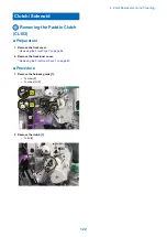
Page 130: ...the front cover Removing the Front Cover on page 94 2 Remove the front inner cover Removing the Front Inner Cover on page 95 Procedure 1 Remove the harness guide 1 1 screw 2 1 connector 3 1 2 3 1x 1x 2 Remove the clutch 1 1 clip 2 1 2 4 Parts Replacement and Cleaning 122 ...

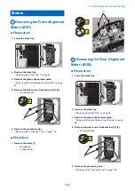
Page 131: ...essing tray Removing the Processing Tray on page 102 Procedure 1 Remove the motor 1 2 screws 2 1 connector 3 1 3 2x 1x 2 Removing the Rear Alignment Motor M108 Preparation 1 Lower the stack tray 2 Remove the stack tray Removing the Stack Tray on page 96 3 Remove the grate shaped lower guide Removing the Grate Shaped Lower Guide on page 96 4 Remove the side covers front and rear 1 2 1 screw 3 each ...

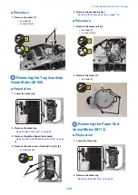
Page 132: ...e Grate Shaped Lower Guide on page 96 4 Remove the side covers front and rear 1 2 1 screw 3 each 3 1 2 2x 5 Remove the processing tray Removing the Processing Tray on page 102 Procedure 1 Remove the motor unit 1 2 screws 2 1 connector 3 1 2 3 2x 1x 2 Remove the motor 1 2 screws 2 2 1 2x Removing the Paper End Assist Motor M113 Preparation 1 Lower the stack tray 2 Remove the stack tray Removing the...

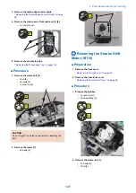
Page 133: ... 3 1 connector 4 2x 1x 1 2 3 4 CAUTION Do not forget to hook the tensioner when installing the belt 2 Remove the motor 1 2 screws 2 1 2 2x Removing the Stapler Shift Motor M114 Preparation 1 Remove the front cover Removing the Front Cover on page 94 2 Remove the front inner cover Removing the Front Inner Cover on page 95 Procedure 1 Process the harness 2 connectors 1 3 wire saddles 2 3x 2x 2 1 2 R...

Page 134: ...rear cover Removing the Rear Cover on page 94 2 Remove the staple free binding unit 1 Removing the Staple Free Binding Unit on page 109 Procedure 1 Process the harness 1 1 connector 2 1 2 1x 1x 2 Remove the harness guide 1 1 screw 2 2 claws 3 1 2 3 1x 3 Remove the encoder and screws 1 encoder 1 2 screws 2 2 2x 1 4 Parts Replacement and Cleaning 126 ...

Page 135: ...the saddle unit service position Pulling Out the Saddle Unit Service Position on page 131 Procedure 1 Remove the motor cover 1 2 screws 2 2x 2 1 2 Process the harness 2 connectors 1 1 wire saddles 2 1x 2x 1 2 3 Remove the motor unit 1 3 screws 2 1 spring 3 1 belt 4 2 3 1 4 2 3x 4 Remove the motor 1 2 screws 2 4 Parts Replacement and Cleaning 127 ...

Page 136: ...Out the Saddle Unit Service Position on page 131 Procedure 1 Remove the motor cover 1 2 screws 2 2x 2 1 2 Process the harness 2 connectors 1 1 wire saddles 2 1 2 2x 1x 3 Remove the motor unit 1 1 spring 2 3 screws 3 1 belt 4 2 3 1 3 4 3x 4 Remove the motor 1 2 screws 2 2x 1 2 2 4 Parts Replacement and Cleaning 128 ...

Page 137: ... the switch 1 1 connector 2 1 2 1x Removing the Swing Guide Safety Switch SW102 Preparation 1 Remove the front cover Removing the Front Cover on page 94 2 Remove the front inner cover Removing the Front Inner Cover on page 95 3 Remove the rear cover Removing the Rear Cover on page 94 4 Remove the escape tray Removing the Escape Tray on page 96 5 Remove the grate shaped guide Removing the Grate sha...

Page 138: ...emoving the Front Cover on page 94 2 Remove the front inner cover Removing the Front Inner Cover on page 95 Procedure 1 Disassemble the front inner cover 1 3 screws 2 3x 1 1 2 2 2 Remove the switch holder 1 1 screw 2 1x 1 2 3 Remove the switch PCB 1 1 screw 2 1 connector 3 1x 1x 1 2 3 4 Parts Replacement and Cleaning 130 ...

Page 139: ...r on page 94 4 Remove the escape tray Removing the Escape Tray on page 96 Procedure 1 Remove the grate shaped guide 1 2 screws 2 2 hooks 3 1 3 2 2x Removing the Escape Delivery Roller Preparation 1 Remove the front cover Removing the Front Cover on page 94 2 Remove the front inner cover Removing the Front Inner Cover on page 95 3 Remove the rear cover Removing the Rear Cover on page 94 4 Remove th...

Page 140: ... the drive support plate the drive shaft 4 may drop Be sure to hold the drive shaft 4 3 4 4x 1 2 1x 2 3 Remove the drive shaft 1 1 shaft support 2 1 belt 3 1 washer 4 1 bearing 5 2 3 4 5 1 4 Remove the E ring 2 E rings 1 1 1 5 Remove the gear 1 1 claw 2 1 2 4 Parts Replacement and Cleaning 132 ...

Page 141: ...x 9 Remove the shaft support 1 1 10 Pull out the escape delivery slave shaft 1 about 3cm for the arrow direction A Be sure not to remove the shaft 1 from the front frame CAUTION When pulling out the escape delivery slave shaft the gear 2 may drop Be sure to hold the gear 2 1 gear 2 1 A 2 4 Parts Replacement and Cleaning 133 ...

Page 142: ...ping the slide drive holder 1 Pull out the escape delivery roller 3 for the arrow direction 1 shaft support 2 3 2 1 NOTE Since the escape delivery roller comes in contact with the sensor flag 2 and guide 3 be sure to escape the sensor flag 2 and guide 3 1 Removing the Return Roller Preparation 1 Lower the stack tray 2 Remove the stack tray Removing the Stack Tray on page 96 3 Remove the grate shap...

Page 143: ... clips 2 shaft support 2 2 1 1 2 Remove the return roller 2 from link part 1 1 1 2 Removing the Swing Roller Procedure 1 Lower the stack tray 2 Spread the escape roller holder 1 to the arrow in the figure to remove the escape roller unit 2 CAUTION When removing the swing roller unit the shaft support may remove and drop 1 2 3 Remove the shaft support 1 and remove the clips 2 2 shaft support 1 3 cl...

Page 144: ...e 2 Align the paddle end face 3 with the shaft end face 4 1 1 2 1 4 3 1 2 4 3 Removing the Folding Roller Preparation 1 Remove the saddle unit Removing the Saddle Unit on page 105 2 Remove the saddle stitcher controller PCB Removing the Saddle Stitcher Controller PCB PCB201 on page 118 Procedure 1 Remove the PCB holder 1 4 connectors 2 2 screws 3 4x 2x 1 3 2 2 2 2 Remove the saddle upper guide 1 2...

Page 145: ...ght pin 3 1 shaft support 4 4 3 2 1 5 Remove the drive shaft 1 1 shaft support 2 1 2 6 Remove the motor cover 1 2 screws 2 1 2 2x 7 Remove the wire saddle 4 wire saddles 4x 8 Remove the drive support plate 1 3 screws 2 1 shaft support 3 4 Parts Replacement and Cleaning 137 ...

Page 146: ...0 Remove the delivery motor gear 1 gear 1 1 belt 2 2 1 11 Remove the folding drive support plate 1 3 screws 2 2 3x 1 2 12 Remove the drive gear 2 gear 13 Remove the gear of the folding roller upper lower 2 C ring 2 2 gear 1 1 2 4 Parts Replacement and Cleaning 138 ...

Page 147: ...ove the saddle upper guide 1 1 connector 2 4 screws 3 3 3 3 3 4x 1 2 1x 17 Remove the delivery guide base 1 2 screws 2 1 2 2 2x 18 Remove the saddle exit roller 1 1 E ring 2 2 shaft support 3 2 3 3 1 19 Remove the saddle delivery guide support plate 1 2 screws 2 4 Parts Replacement and Cleaning 139 ...

Page 148: ...the E ring 1 and shaft support 2 1 2 23 Remove the spring of the roller tensioner front 1 1 24 Remove the bearing 2 C ring 2 2 bearing 1 2 1 25 Loosen fixed screw of stitcher unit 4 screws CAUTION When loosening the Fixation Screw be sure to check the Fixation Position scale 4 Parts Replacement and Cleaning 140 ...

Page 149: ...ont cover Removing the Lower Front Cover on page 94 3 Remove the saddle unit Removing the Saddle Unit on page 105 4 Remove the pushing unit Removing the pushing plate on page 141 Procedure 1 Removing the pushing plate 1 1 pushing plate guide 2 3 screws 3 CAUTION When removing the pushing plate be sure to check the fixation position scale 1 2 3 3 3 3x Handling after parts replacement 1 If you remov...

Page 150: ...Adjustment 5 Overview 143 Basic Adjustment 148 Adjustments When Replacing Parts 173 Other 184 ...

Page 151: ...on of the saddle stitcher unit thin paper SDL FLD2 When the folding position of the saddle stitcher unit is displaced with the thin paper Adjusting the alignment width of the saddle stitcher unit SDL ALG When the misalignment occurs within a pa per stack on the saddle stitcher unit Adjusting the A4 size paper align ment position ST ALG1 When misalignment occurs in A4 size pa per Adjusting the LTR ...

Page 152: ...f paper stack oc curs during alignment operation on the pro cessing tray Adjusting the height of the return belt 3 RBLT PS3 When the misalignment of paper stack oc curs during alignment operation on the pro cessing tray Adjusting the front rear staple posi tion at the manual staple mode MSTP 2P When the staple position for front rear di rection is displaced at the manual staple mode Adjusting the ...

Page 153: ...ntroller PCB PUN BK W When replacing the puncher controller PCB This mode is available when the puncher unit has been installed Functional setting items Items Service Mode SORTER OP TION Use case Remarks Setting ON OFF of the buffer oper ation BUFF SW When the misalignment of the buffered pa per stack occurs on the processing tray When the buffer operation is set to OFF productivity is de creased ...

Page 154: ...ON the pro ductivity is decreased When setting the punch mode to the precision priority this mode enables This mode is available when the puncher unit has been in stalled Basic Adjustment Items No Items Use case Refer to 1 Adjusting the Paper Alignment Adjusting Stacker Alignment Position When misalignment occurs in front rear di rection Adjusting Stacker Align ment Position on page 149 2 Adjustin...

Page 155: ...he sad dle stitch mode Adjusting the Saddle Stitch Position on page 171 Adjustments When Replacing Parts Items No Target part Adjustment item and description Refer to 1 Stack Tray Drive Belt Align the phase of the belt installation position Phase Alignment When Installing the Stack Tray Drive Belt on page 173 2 Swing Unit Align the phase of the swing unit installation position and fix them in plac...

Page 156: ...sition When the staple position in front rear di rection is displaced in the front rear 1 sta pling mode or 2 stapling mode Adjusting the Staple Po sition on page 158 7 Adjusting the Stapler Unit Installation Position When the stapler unit is replaced When the staple position in feed di rection is displaced in the front rear 1 stapling mode or 2 stapling mode Adjusting the Stapler Unit Installatio...

Page 157: ...After the setting value is changed write the changed value in the service label 1 Adjust the stacker alignment position by the following service modes Adjustment of A4 size paper SORTER ADJUST ST ALG1 Adjustment of LTR size paper SORTER ADJUST ST ALG2 Feed Direction Alignment Plate Adjustment range 50 to 50 Unit 0 1mm As the value is incremented by 1 the position of the adjustment plate is increas...

Page 158: ...completion of the adjustment remove paper on the processing tray Adjusting Center Alignment Standard Position Use case When the standard position for the center alignment is misaligned When misalignment occurs in front rear direction Feed Direction Feed Direction Procedure of adjustment CAUTION This adjustment influences alignment operation and staple position Adjust the alignment width with Adjus...

Page 159: ...0 to 50 Unit 0 1mm As the value is incremented by 1 the standard position for the center alignment moves by 0 1 mm Toward rear Toward front Right Angle Adjustment of Alignment Plate Use case When remove or replace the alignment plate When the paper alignment position is displaced Feed Direction Feed Direction Procedure of adjustment 5 Adjustment 151 ...

Page 160: ...r Paper End Retainer 2 Loosen the screws of the alignment plate front and rear adjust the alignment plate so that it is parallel with the paper and then tighten the screws 2x 2x Paper Fixing Screw Fixing Screw Front Alignment Plate Rear Alignment Plate 3 Widen the front alignment palte approx 10mm 5 Adjustment 152 ...

Page 161: ...ustment of alignment plate again Paper 10 mm A B Front Alignment Plate 5 Widen the rear alignment palte approx 10mm 6 Contact a sheet of paper with the rront alignment plate to check the gaps between the alignment plate and a sheet of paper at A and B portion In the case the gap is large adjust the right angle adjustment of alignment plate again A B Paper Rear Alignment Plate 10 mm 5 Adjustment 15...

Page 162: ... by the following service modes When the paper displacement occurs on the 1st to 2nd sheets of buffered paper SORTER ADJUST BFF SFT When the paper displacement occurs on the 2nd to 3rd sheets of buffered paper SORTER ADJUST BFF SFT2 1st sheet 2nd sheet 3rd sheet Feed Direction Adjustment range 60 to 60 Unit 0 1mm As the value is incremented by 1 the paper position moves by 0 1mm The 1st sheet of b...

Page 163: ...tment value SORTER OPTION BUFF SW 0 1 After setting 0 for the buffer adjustment value adjust height of Swing Unit and Return Roller Adjusting the Return Roller Swing Unit Height on page 155 Adjusting the Return Roller Swing Unit Height Use case When misalignment occurs in feed direction When misalignment occurs by failure of the paper feeding to processing tray Feed Direction Feed Direction Proced...

Page 164: ...In the case the paper is NOT fed by return roller The return roller does not contact the paper Adjust the swing unit height by the following service mode Input plus value and check again SORTER ADJUST SW UP RL Feed Direction Swing Unit Adjustment range 30 to 30 Unit 0 1 degree As the value is incremented by 1 the height of the swing unit is changed by angle of 0 1 degree Downward Upward 5 Adjustme...

Page 165: ...se the paper does not hit the processing tray stopper Adjust return roller height 1 sheet by the following service mode Input plus value and check again SORTER ADJUST RBLT PS3 NOTE Return roller height is changed during paper alignment in this mode Feed Direction Return Roller Adjustment range 50 to 100 Unit 0 1 degree As the value is changed by 1 the height of the return belt changes by angle of ...

Page 166: ...nges by angle of 0 1 degree Downward Upward Adjusting the Staple Position Adjusting the Staple Position Use case When the staple position in front rear direction is displaced in the front rear 1 stapling mode or 2 stapling mode Feed Direction Feed Direction Front stapling Rear stapling 2 point stapling Procedure of adjustment NOTE After the setting value is changed write the changed value in the s...

Page 167: ...ear stapling 2 point stapling Adjustment range 30 to 30 Unit 0 1mm As the value is incremented by 1 the staple position moves by 0 1mm Toward rear Toward front Adjusting the Stapler Unit Installation Position Use case When the stapler unit is replaced When the staple position in feed direction is displaced in the front rear 1 stapling mode or 2 stapling mode Feed Direction Feed Direction Front sta...

Page 168: ...tion fix the stapler unit support plate by matching to the mark Stapler Unit Mounting Plate 2 Loosen the two screws of the stapler unit support plate adjust the stapler installation position by referring to the scale and then tighten the screws Feed Direction Paper Stapler Unit Mounting Plate Fixing Screw Fixing Screw 5 Adjustment 160 ...

Page 169: ... adjustment NOTE After the setting value is changed write the changed value in the service label 1 Adjust the staple free binding position by the following service modes SORTER ADJUST FR STP Y Feed Direction Adjustment range 20 to 15 Unit 0 1mm As the value is changed by 1 the staple position moves by 0 1 mm Toward rear Toward front 5 Adjustment 161 ...

Page 170: ...g the Saddle Paper End Stopper Installation Angle Use case If the fold position of the paper stack delivered from the saddle stitcher unit is skewed Feed Direction B B Folding Position Feed Direction B B Folding Position 5 Adjustment 162 ...

Page 171: ...t the saddle stitcher unit 2 until it stops 1 2 2 Push the plate spring left right 2 and then pull the saddle stitcher unit 1 to the service position 2 2 1 3 Remove the 2 screws and then remove the lower right saddle cover 2x 4 Loosen the 3 screws 3x 5 Adjustment 163 ...

Page 172: ...dle Stitch Fold Position Adjustment Maintenance Adjust Action Adjust Fold Position NOTE After the setting value is changed write the changed value in the service label 1 Find the displaced paper in the paper stack In the case the last paper is displaced Change the setting of the paddle operation when stacking paper by the following service mode SORTER OPTION SDL ALG 1 NOTE In this mode the paddle ...

Page 173: ...er by the following service mode SORTER ADJUST SDL FLD2 Feed Direction B B Folding Position Adjustment range 20 to 20 Unit 0 1mm As the value is incremented by 1 the fold position moves by 0 1 mm The fold position moves toward the left at open page of the book The fold position moves toward the right at open page of the book Adjusting the Saddle Alignment Plate Position Use case When misalignment ...

Page 174: ...mm As the value is incremented by 1 the alignment width is increased by 0 1 mm The width of the adjustment plate becomes narrow The width of the adjustment plate becomes wide NOTE In the case the misalignment occurs after adjusting the Saddle Alignment Plate Position Check the following items and adjust again Check the connection between finisher and host machine Adjust side registration of host m...

Page 175: ...nstallation Position Use case When the stitch positions of the front and rear sides become misaligned If you remove or replace the stitcher unit Feed Direction B B Stapling Position Feed Direction B B Stapling Position Procedure of adjustment 5 Adjustment 167 ...

Page 176: ...1 Mark the installation position of the stitcher unit NOTE If returning its installation position to the original position fix the stitcher unit by matching to the mark Stitcher Unit 5 Adjustment 168 ...

Page 177: ...cher unit adjust the installation position by referring to the scale and then tighten the screws NOTE Normally install so that the stitcher unit mark is aligned to the center of the support plate scale Stitcher Unit Mark 5 Adjustment 169 ...

Page 178: ...A B Feed Direction Stapling Position Fixing Screw A B Stitcher Unit Fixing Screw Fixing Screw Mark 5 Adjustment 170 ...

Page 179: ...B Stapling Position Procedure of adjustment CAUTION In the case performing this adjustment record user mode setting value before the adjustment Input 0 for setting value and start the adjustment Adjustment Maintenance Adjust Action Change Fold Stitch Position NOTE After the setting value is changed write the changed value in the service label 5 Adjustment 171 ...

Page 180: ...itcher when using the thin paper the paper that the paper weight is less than 64 g m2 adjust the saddle stitch position by the following service mode SORTER ADJUST SDL STP2 Feed Direction B B Stapling Position Adjustment range 20 to 20 Unit 0 1mm As the value is incremented by 1 the staple position moves by 0 1mm The staple position moves toward the left at open page of the book The staple positio...

Page 181: ...the protrusions of the belt holder front and rear attached to the stack tray drive belt to the marks on the support plate and fix them in place Clearance 2 5 mm or less Belt Holder Front Mark Belt Holder Rear Upper part of Protrusion Mark Upper part of Protrusion Phase Alignment When Installing the Swing Unit If you remove or replace the swing unit align the phase of the swing unit installation po...

Page 182: ...t Gear Swing Guide Unit Up Down Arm Rear Gear Phase adjustment of paddle unit If you remove or replace the swing unit perform phase adjustment of paddle unit Checking Phase Angle of Paddle Unit 1 Make a print to have a sheet of paper ejected on the stack tray and the paddle unit will stop at its home position 2 Lower the stack tray 5 Adjustment 174 ...

Page 183: ... in between the line A and B A B 1 CAUTION Adjust the phase angle of the paddle unit if the paddle blade is not in between the 2 lines CAUTION There are 2 paddle blades So do not take the wrong blade to confirm its position 5 Adjustment 175 ...

Page 184: ... Adjsting Phase Angle of the Paddle Unit 1 Put off the belt 1 1 2 Lower the swing roller till its end 5 Adjustment 176 ...

Page 185: ...hat it becomes in parallel with the line B CAUTION There are 2 paddle blades So do not take the wrong blade to confirm its position CAUTION Do not have the paddle blade be in parallel with the line A or the adjustment fails A B 1 5 Adjustment 177 ...

Page 186: ...4 Align the projection of the sensor flag gear 1 with the mark off line 2 1 2 5 Turn the sensor flag gear in the arrow direction by the amount of 1 tooth 1 2 5 Adjustment 178 ...

Page 187: ...ly and the phase angle of the paddle blade gets wrong NOTE Check the phase angle of the paddle unit again after performing this adjustment Phase Alignment When Installing the Paper Folding Roller If you remove or replace the paper folding roller align the phase of the paper folding roller installation position 5 Adjustment 179 ...

Page 188: ...ON FIN BK R 2 To execute back up turn the main power on the host machine off and then on 3 Turn the main power of the host machine off When backup is not possible 1 Before replacing the finisher controller PCB output P PRINT in the host machine s service mode Lv 1 COPIER FUNCTION MISC P P PRINT 2 Turn the main power of the host machine off Handling after replacement NOTE If the finisher version is...

Page 189: ...ition BFF SFT Adjusting the displacement amount of the buffered paper 1st to 2nd sheets BFF SFT2 Adjusting the displacement amount of the buffered paper 2nd to 3rd sheets SDL STP Adjusting the stitching position of the saddle stitcher unit SDL FLD Adjusting the folding position of the saddle stitcher unit SDL ALG Adjusting the alignment width of the saddle stitcher unit ST ALG1 Adjusting the A4 si...

Page 190: ...ng the staple timing at the manual staple mode PNCH SW3 Setting ON OFF of the mode to improve the precision of the punch hole position SFT CHNG Setting the delivery number of the stacking paper at the shift sort mode STP ALG Setting the operation of the alignment plates at the staple and sta plefree binding mode SDL ALG Setting the paddle operation when stacking the paper in the saddle stitcher un...

Page 191: ...2 Set all SW1 keys set to OFF ON 1 2 3 4 SW1 SW2 3 Enter the values written to the service label affixed to the front cover 5 Adjustment 183 ...

Page 192: ...city when stacking in the saddle delivery tray Release procedure 1 Pull the paper stopper of the saddle delivery tray out slightly and lower it NOTE When the paper stopper is lowered the sensor flag of the saddle delivery tray paper sensor PS216 is also lowered in sync and paper detection on the tray is disabled Paper Stopper 5 Adjustment 184 ...

Page 193: ...Troubleshooting 6 Making Initial Checks 186 Processing Tray Area 187 Saddle Stitcher Area 188 ...

Page 194: ...in a place of direct sunlight 5 The machine is installed in a well ventilated place where the machine stands horizontally Checking the paper 6 Paper does not absorb moisture or dry out Set paper by taking it out from a new package to output Checking the con sumable parts 7 Check the list of estimated life of consumable parts and replace parts that have reached the estimated life Checking the peri ...

Page 195: ...t of Alignment Plate When remove or replace the align ment plate When the paper alignment position is displaced Right Angle Adjustment of Alignment Plate on page 151 4 Adjusting Delivery of Staple Stack When the paper displacement occurs on the 1st to 2nd sheets of buffered paper Adjusting Delivery of Sta ple Stack on page 154 5 Adjusting the Return Roller Swing Unit Height When misalignment occur...

Page 196: ...on Front Rear direction No Items Use case Refer to 1 Adjusting the Fold Position Adjusting the Saddle Paper End Stopper Installation Angle If the fold position of the paper stack deliv ered from the saddle stitcher unit is skewed Adjusting the Saddle Paper End Stopper Installation An gle on page 162 2 Adjusting the Fold Placement When misalignment occurs in feed direc tion Adjusting the Fold Place...

Page 197: ...rocedure 190 Checking Before Installation 191 Unpacking 195 Checking the Contents 198 Installation Procedure 199 Affixing the Labels 208 Making Adjustments 209 Making Checks After Completion of Installation Work 213 Detaching from the Host Machine 214 ...

Page 198: ...rations used in this procedure are those of Booklet Finisher unless otherwise specified Product Name Safety regulations require the product s name to be registered In some regions where this product is sold the following names may be registered instead F281187 F281188 7 Installation 190 ...

Page 199: ...site Therefore it is recommended to see the installation site in advance before delivering this Equipment to the user s site Checking the Installation Space The space required for installation and maintenance work is shown below 100mm 500mm 500mm or more or more or more 7 Installation 191 ...

Page 200: ... 500mm 1 160mm 760mm 850mm 1 945mm 525mm 660mm 760mm Finisher Slope Board Pallet Check Items When Turning OFF the Main Power Check that the main power switch is OFF 1 Turn OFF the main power switch of the host machine 2 Be sure that Control Panel Display and Main Power Lamp are both turned OFF and then disconnect the power plug 7 Installation 192 ...

Page 201: ...to perform the work in accordance with the standard to handle a heavy load in each country When moving this Equipment after having unpacked it be careful by placing a plate etc on areas with steps to prevent the casters from hitting those steps If the casters hit a step the casters or the base plate may be deformed CAUTION When tightening the screws do not tighten them too tightly Otherwise there ...

Page 202: ...t 3 Staple Finisher Booklet Finisher NOTE When installing the following options at the same time be sure to install them before installing this equipment Refer to each installation procedure 3 Way Unit Super G3 2nd Line Fax Board Super G3 FAX Board Buffer Pass Unit Puncher Unit Puncher Unit Booklet Finisher Staple Finisher 7 Installation 194 ...

Page 203: ...r be sure to take full care not to let it tumble over Weight Staple Finisher approx 40kg Booklet Finisher approx 64kg NOTE This Equipment is secured by tapes cushioning and other materials to protect it from vibration and impact during transit Remove all such tapes and cushioning materials as instructed below before installing this Equipment 1 2 3 7 Installation 195 ...

Page 204: ...4 5 6 7 8 9 7 Installation 196 ...

Page 205: ...10 7 Installation 197 ...

Page 206: ... RS Tightening M3 x 8 2 pcs 5 Screw W Sems M3 x 6 1 pc 6 Screw Binding M3 x 25 1 pc 7 Screw TP M3 x 6 3 pcs 8 Grounding rail 1 pc 9 Stapler Unit Staple Case 1 pc 10 Tray Setting Label 1 pc 11 Jam Label Booklet Finisher only 1 pc 12 Jam Language Label Booklet Finisher only 1 pc 13 Saddle Caution Language Label Booklet Finisher only Others Including guides 7 Installation 198 ...

Page 207: ...r switch is OFF and the power plug is disconnected from the outlet Preparing the Host Machine for Installation 1 CAUTION When the Full Detection Flag has been installed already be careful not to damage the Full Detection Flag 2 3 1x 4 2x 7 Installation 199 ...

Page 208: ...e Cover will be used in step 9 6 NOTE The removed Face Cover will be used in step 8 7 NOTE When the Tray Guide supplied for Host Machine is installed remove it The removed Tray Guide will be used in step 8 7 Installation 200 ...

Page 209: ...8 Attach the Face Covers removed in step 6 to the Tray Guide supplied for Host Machine or removed in step 7 9 Attach the Face Covers removed in step 5 to the Tray Guide 10 Claw Claw 7 Installation 201 ...

Page 210: ...11 NOTE Keep the parts as illustration above Installation of Buffer Pass Unit 1 7 Installation 202 ...

Page 211: ... between the Buffer Pass Unit and the Inner Rear Cover of the Host Machine 3 2x 4 Push the Buffer Pass Unit toward the Inner Rear Cover of the Host Machine until it stops and then slide the Buffer Pass Unit toward the paper delivery unit until the latch is surely engaged NOTE If the Buffer Pass Unit has to be removed from the Host Machine refer to the Detaching from the Host Machine 7 Installation...

Page 212: ...x NOTE The removed screw is used at Step 7 7 Fix the screw removed in Step 6 to the original position 1x 8 Fix the Latch Plate with a bundled screw 4pcs 4x 56 7LJKWHQLQJ 0 LQGLQJ 0 6HPV 0 7 Installation 204 ...

Page 213: ...Machine relocate it to the Finisher Connecting to Host Machine 1 CAUTION When connecting the Interface Cable be sure to turn off the Host Machine and disconnect its power cable from the outlet 1x 2 NOTE If the positioning pin of the Buffer Pass Unit is not fitted the positioning hole on the Finisher carry out the adjustment described in Adjusting the Height 7 Installation 205 ...

Page 214: ...3 TP M3㹶6 1x 4 NOTE Staple Finisher only 5 Pull out the Saddle Unit about 150mm Booklet Finisher only 7 Installation 206 ...

Page 215: ...6 Loosen 2 screws and then fix the Saddle Unit Auxiliary Caster so that its Caster can touch the floor Booklet Finisher only 2x 2x 7 Installation 207 ...

Page 216: ...guage Label Booklet Finisher only 1 2 Affix the Label in the appropriate language 3 Affix the Label in the appropriate language 4 Tray Setting Labels 1 Affix the supplied which is specified by user in the frame line of Tray Labels 7 Installation 208 ...

Page 217: ...on of the Finisher Check the height and tilt and adjust it as required Be sure to adjust as necessary Making Check and Adjustment of the Height 1 Check the difference in height between the Finisher and the Host Machine Make sure that the pin of the Buffer Pass Unit inserts into the hole of the Finisher In the case the pin of Buffer Pass Unit is inserted into the hole of the Finisher this adjustmen...

Page 218: ...B NOTE If the adjustment dial keeps lifting upward lower the adjustment dial by releasing three claws And be sure to insert the three pins of the adjustment dial to the hole of the caster support plate Claw Claw Claw Making Check and Adjustment of the Tilt 1 Check the relational tilting amount of the Finisher and Host Machine Make sure that the gap between the right side of the Finisher and the le...

Page 219: ...the height of the Finisher by 2 0 mm To tilt the Finisher to the right turn the dial in the direction of arrow A To tiltthe Finisher to the left turn the dial in the direction of arrow B NOTE Adjust the tilt at 2 left casters A B B A NOTE If the adjustment dial keeps lifting upward lower the adjustment dial by releasing three claws And be sure to insert the three pins of the adjustment dial to the...

Page 220: ...Checks After Completion of Adjustments 1 Check to see that the difference in height between within the specifications If they are not within the specifications make adjustments again 2 1x 3 7 Installation 212 ...

Page 221: ...inisher only 1 pc Operation Check 1 Turn ON the main power of the Host Machine 2 3 4 If a message prompting the user to update the version appears press Update to automatically update the version of the Finisher NOTE If Skip is selected a message prompting the user to update the version will appear every time the Host Machine is started In the service mode Level 2 shown below it is possible to set...

Page 222: ... power cord prior to connection of the interface cable to avoid any unexpected electric shock Finisher 1 1x 2 3 CAUTION When disconnecting the Interface Cable be sure to turn off the Host Machine and disconnect its power cable from the outlet 1x Buffer Pass Unit 1 5x 7 Installation 214 ...

Page 223: ...2 3 2x 7 Installation 215 ...

Page 224: ...APPENDICES Service Tools 217 General Circuit Diagram 218 ...

Page 225: ...ar fire Procure locally Substitute IPA isopropyl alcohol 2 Solvent Cleaning e g metal oil or toner stain Fluoride family hydrocar bon Chlorine family hydrocar bon Alcohol Do not bring near fire Procure locally Substitute MEK 3 Lubricating oil EM 50L Tool No HY9 0007 Lubrication e g gears drive areas friction areas Special oil Special solid lubricatiing agent Lithium soap Special Tools None Service...

Page 226: ... 4 5 6 7 13 12 11 8 9 10 1 2 3 4 5 6 7 13 8 9 1 2 3 4 5 6 7 1 2 3 4 5 1 2 3 4 1 2 8 1 2 3 4 5 6 7 8 1 2 3 4 5 6 7 1 2 1 2 1 2 3 1 2 3 1 2 3 1 2 3 1 2 12 11 8 9 10 1 2 3 4 5 6 7 1 2 3 4 5 6 7 1 2 3 4 1 2 3 1 2 3 4 5 6 7 1 2 3 1 2 3 1 2 3 1 2 3 4 1 2 3 1 2 3 1 2 3 1 2 3 1 2 3 1 2 3 1 2 3 1 2 3 1 2 1 2 13 12 11 8 9 10 1 2 3 4 5 6 7 14 1 2 3 4 1 2 3 4 1 2 3 4 1 2 3 4 1 2 3 4 1 2 3 4 13 12 11 8 9 10 1 ...

Page 227: ...2 3 1 2 3 1 2 3 1 2 3 1 2 3 8 9 1 2 3 4 5 6 7 1011 12 8 9 1 2 3 4 5 6 7 1011 12 8 9 10 1 2 3 4 5 6 7 11 12 1 2 3 1 2 3 1 2 3 1 2 3 1 2 3 1 2 3 1 2 3 1 2 3 8 9 1 2 3 4 5 6 7 1011 12 13 15 16 14 8 9 1 2 3 4 5 6 7 1011 12 8 9 10 1 2 3 4 5 6 7 11 12 1 2 3 4 1 2 3 4 1 2 3 4 1 2 3 4 1 2 3 4 1 2 3 4 1 2 3 4 5 6 1 2 3 4 5 6 1 2 3 4 1 2 3 4 1 2 1 2 3 4 1 2 3 4 1 2 3 4 1 2 1 2 1 2 1 2 3 4 5 6 1 2 3 1 2 3 1 ...

Page 228: ...9 10 11 12 13 14 15 16 17 18 GND 1 4 3 2 TJ101D TJ101DH 3 2 1 3 TJ111D TJ111DH 3 1 2 1 3 2 TJ051 2 1 3 2 3 2 1 TJ052 1 3 2 1 TJ061 TJ021DH 19 Host Machine 11 12 13 14 15 16 17 18 TJ021D 7 1 6 5 4 3 2 8 9 10 4 5 3 2 1 TJ204C TJ204AB 8 1 2 3 4 5 6 7 DJ32 14 13 12 11 8 1 2 3 4 5 6 7 9 10 2 3 4 1 14 13 12 11 10 9 8 2 3 4 5 6 1 7 2 1 TJ12 TJ04 TJ13 2 3 4 1 TJ08 TJ081DH 2 3 4 1 TJ081D 3 2 1 3 2 1 6 5 4 ...

Reviews:

Related manuals for Staple Finisher-AA1