COPYRIGHT© 2002 CANON INC.
2000
CANON BOOKLET TRIMMER-A1 REV.0 FEB. 2002
CHAPTER 3 MECHANICAL SYSTEMS
3-37
6.2 Removing the Holder Sensor Unit (Holder upper limit sen-
sor PS110, Holder lower limit sensor PS111)
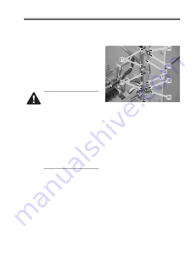
1) As shown in 1.3, remove the rear cover.
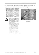
2) Remove the 2 screws [1], and discon-
nect the connector [2]; and remove the
sensor holding plate (upper) [3], then,
detach the upper limit sensor PS110 [4].
Remove the 2 screws [5], and discon-
nect the connector [6]; and remove the
sensor holding plate (lower) [7], then,
detach the lower limit sensor PS111 [8].
You need to adjust the position
when mounting the holder sen-
sor (upper limit sensor or lower
limit sensor); perform either of
the following two:
i. Before removing the sensor
mounting plate [3, 4], mark
its current position on the
chassis using a pen or the
like; then, mount new one
back with reference to the
marking.
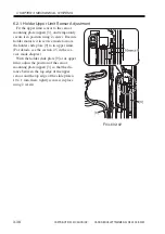
ii. After removing the sensor
mounting plate [3, 4], make
the following adjustments:
F03-602-01
Summary of Contents for Two-Knife Booklet Trimmer-A1
Page 129: ...COPYRIGHT 2002 CANON INC 2000 CANON BOOKLET TRIMMER A1 REV 0 FEB 2002 CHAPTER 6 APPENDIX ...
Page 132: ...User Mode COPYRIGHT 2002 CANON INC 2000 CANON BOOKLET TRIMMER A1 REV 0 FEB 2002 ...
Page 141: ...Service Mode COPYRIGHT 2002 CANON INC 2000 CANON BOOKLET TRIMMER A1 REV 0 FEB 2002 ...

