background image

COPYRIGHT© 2002 CANON INC.

 2000 

CANON BOOKLET TRIMMER-A1 REV.0 FEB. 2002

CHAPTER 2 BASIC OPERATIONS

2-29

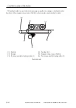
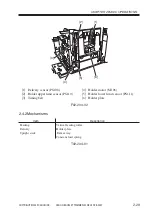
[1] Delivery sensor (PS108)
[2] Holder upper limit sensor (PS110)
[3] Timing belt

[4] Holder motor (M106)
[5] Holder lower limit sensor (PS111)
[6] Holder plate

F02-204-02

2.4.2 Mechanisms

T02-204-01

[6]

[1]

[2]

[3]

[4]

[5]

Item

Description

Feeding

Vertical feeding roller

Delivery

Holder plate

Upright stack

Deliver tray

Constant load spring

Summary of Contents for Two-Knife Booklet Trimmer-A1

Page 1: ...FEB 2002 FY8 13HG 000 BOOKLET TRIMMER A1 REVISION 0 COPYRIGHT 2002 CANON INC 2000 CANON BOOKLET TRIMMER A1 REV 0 FEB 2002 PRINTED IN U S A IMPRIME AU U S A ...

Page 2: ...in the contents of this manual over a long or short period Canon will issue a new edition of this manual The following paragraph does not apply to any countries where such provisions are inconsistent with local law Trademarks The product names and company names used in this manual are the registered trademarks of the individual companies Copyright This manual is copyrighted with all rights reserve...

Page 3: ...iring care to avoid combustion fire Indicates an item prohibiting disassembly to avoid electric shocks or problems Indicates an item requiring disconnection of the power plug from the electric outlet Indicates an item intended to provide notes assisting the understanding of the topic in question Memo Indicates an item of reference assisting the understanding of the topic in ques tion REF Provides ...

Page 4: ... eration mode machine operation basic construction Chapter 2 Basic Operations basic operation mechanism control Chapter 3 Mechanical Systems disassembly assembly adjustment Chapter 4 Maintenance and Inspection periodically replaced parts periodically cleaned parts periodically inspected parts Chapter 5 Troubleshooting PCBs software upgrading error code jam code Chapter 6 Appendix general circuit d...

Page 5: ...f a given signal is High while 0 is used to indicate Low The voltage value however differs from circuit to circuit In addition the asterisk as in DRMD indicates that the DRMD signal goes on when 0 In practically all cases the internal mechanisms of a microprocessor cannot be checked in the field Therefore the operations of the microprocessors used in the ma chines are not discussed they are explai...

Page 6: ...r Press 2 18 2 3 Controlling the Trimmer Assembly 2 21 2 3 1 Construction 2 21 2 3 2 Mechanisms 2 23 2 3 3 Controlling the Trimming Operation 2 23 2 3 4 Removing the Waste Paper 2 24 2 3 5 Controlling the Trimmer 2 24 2 3 6 Removing the Waste Paper 2 26 2 4 Stacker Assembly 2 28 2 4 1 Construction 2 28 2 4 2 Mechanisms 2 29 2 4 3 Delivery 2 30 2 4 4 Upright Stacking 2 32 2 4 5 Controlling the Deli...

Page 7: ...ng the Stacker Cover Sensor PS114 and the Stacker Cover Switch MS3 MS4 3 23 5 Press Assembly 3 25 5 1 Removing the Upper Press Assembly 3 25 5 2 Removing the Upper Press Assembly Feeding Belt 3 26 5 3 Removing the Lower Press Assembly 3 26 5 3 1 Parallelism Adjustment between the Folding Face and the Trimming Face 3 29 5 4 Removing the Stopper Motor M103 3 30 5 5 Removing the Stopper Release Motor...

Page 8: ...n of the Holder Plate 5 2 2 Upgrading the Software 5 3 3 Error Code 5 4 4 Jam Code 5 12 1 Construction of User Mode U 1 1 1 Overview U 1 1 2 Starting User Mode and Making Selections U 3 1 2 1 Trimmer Control Panel U 3 1 3 Ending User Mode U 4 1 4 Basic Operation U 4 1 4 1 Trimmer Control Panel in user mode U 4 1 5 Others U 4 1 5 1 Backing Up the Data U 4 2 Details of Items U 5 2 1 Trim Width Adjus...

Page 9: ... Making Selections S 2 1 3 Ending Service Mode S 2 1 4 Basic Operation S 3 1 4 1 Trimmer Control Panel in service mode S 3 1 5 Others S 3 SERVICE MODE 1 5 1 Backing Up Data S 3 2 Details of Items S 4 2 1 Version Indication S 4 2 2 Trim Counter S 5 2 3 Operation Mode S 6 2 4 Selecting Factory Setting for Trim Width S 7 2 5 Motor Test S 10 2 6 I O Port Display S 12 ...

Page 10: ...COPYRIGHT 2002 CANON INC 2000 CANON BOOKLET TRIMMER A1 REV 0 FEB 2002 CHAPTER 1 GENERAL DESCRIPTION ...

Page 11: ... 2002 CHAPTER 1 GENERAL DESCRIPTION 1 1 1 Features and Functions The trimmer is equipped with mechanisms to receive a booklet prepared by its host saddle finisher trim to smooth its edge and deposit the result in a stack F01 100 01 Edge being trimmed After trimming ...

Page 12: ...ng 2 mm or more thickness Cutter life 500 000 operations or more Waste paper case 500 sheets approx capacity Allowable curling 10 mm max measurement taken of a stack of 5 delivered sheets Degree of parallel See the table below in relation to folded Degree of parallel A B end Operating Temperature 10 C to 30 C Same as host device environment Humidity 10 to 80 RH Same as host device Size 1321 562 62...

Page 13: ...NON INC 2000 CANON BOOKLET TRIMMER A1 REV 0 FEB 2002 CHAPTER 1 GENERAL DESCRIPTION 1 3 3 Names of Parts 3 1 External View 1 Control panel 2 Trimmer 3 Stacker cover 4 Front cover 5 Rigth front cover F01 301 01 1 2 3 4 5 ...

Page 14: ...COPYRIGHT 2002 CANON INC 2000 CANON BOOKLET TRIMMER A1 REV 0 FEB 2002 CHAPTER 1 GENERAL DESCRIPTION 1 4 1 Stacker cover 2 Stacker unit 3 Front cover 4 Right front cover 5 Top plate F01 301 02 1 2 3 4 5 ...

Page 15: ...ESCRIPTION 1 5 3 2 Cross Section 1 Cutter unit 2 Vertical feeding roller 3 Pusher unit 4 Delivered booklets 5 Delivery tray 6 Stacker 7 Holder assembly 8 Stopper assembly 9 Pressing assembly 10 Waste paper box 11 Entrance feeding assembly 12 Paper path F01 302 01 6 7 8 9 10 11 1 2 3 4 5 12 ...

Page 16: ...ions can be made in service mode See the descriptions for service mode 4 4 Others The language used in the trimmer s control panel can be changed only from the trimmer s control panel The language used in the trimmer s control panel is independent of the language used in its host copier s language i e there is no correlation between the two sets of specifica tions When the machine is operating in ...

Page 17: ... the trim function To be pressed to set release the menu To be pressed when selecting a mode or changing the cut width To be pressed when selecting a mode or changing the cut width TO be pressed to store the settings made LED flashing paper jam cover open stack full waste paper box full not set fault service error Remarks 20 characters 2 lines Only when LOCAL Mode A press while setting a mode will...

Page 18: ...eeding assembly open the front cover and the right front cover then turn the jam releasing knob to remove the jam If a booklet jams in the press assembly open the front cover and keep the press assembly releasing lever up to remove it 1 Front cover 2 Press assembly releasing knob 3 Jam removal releasing lever 4 Right front cover 5 Stacker cover F01 502 01 1 2 3 5 4 ...

Page 19: ...NC 2000 CANON BOOKLET TRIMMER A1 REV 0 FEB 2002 CHAPTER 1 GENERAL DESCRIPTION 1 9 1 Open the front cover F01 502 02 2 Open the right front cover F01 502 03 3 Turn the knob of the feeding assembly counter clockwise F01 502 04 ...

Page 20: ...GENERAL DESCRIPTION 1 10 4 Remove the paper jam F01 502 05 5 Close the right cover When closing the cover be sure to take care so as not to trap your fingers F01 502 06 6 Lift the releasing lever When lifting the lever be sure to take care so as not to trap your fingers F01 502 07 ...

Page 21: ... 0 FEB 2002 CHAPTER 1 GENERAL DESCRIPTION 1 11 7 Remove the paper jam F01 502 08 8 Shift the releasing lever back into its initial position F01 502 09 9 Close the front cover When closing the cover be sure to take care so as not to trap your fingers F01 502 10 ...

Page 22: ... BOOKLET TRIMMER A1 REV 0 FEB 2002 CHAPTER 1 GENERAL DESCRIPTION 1 12 10 Open the stacker cover F01 502 11 11 Remove the paper from the stacker as sembly F01 502 12 12 Remove the paper jam from the rear of the stacker assembly F01 502 13 ...

Page 23: ...n closing the cover be sure to take care so as not to trap your fingers F01 502 14 5 2 1 Correcting the Overstacking Error When the stacker tray overflows with printouts the machine will stop its opera tion Remove the printouts as follows Do not impose a load of 10 kg or more on the stacker assem bly 1 Open the stacker cover F01 502 15 ...

Page 24: ...R A1 REV 0 FEB 2002 CHAPTER 1 GENERAL DESCRIPTION 1 14 2 Remove all paper from the stacker as sembly F01 502 16 3 Close the stacker cover The job will resume automatically When closing the cover be sure to take care not to trap your fin gers F01 502 17 ...

Page 25: ...5 5 2 2 Collecting and Disposing of Waste Paper The waste paper from cutting operation is collected in a waste paper box To dispose of the paper open the front cover shift the waste paper box lever and draw out the waste paper box 1 Front cover 2 Waste paper box handle 3 Waste paper box F01 502 18 1 2 3 ...

Page 26: ...ection pressing section and stacker section 1 Stacker section 2 Pressing section 3 Cutter section 4 Feeding section F01 601 01 The trim process i e paper feeding process differs by the trim Designation Modes Designating method of the trim designation modes are different be tween the trim operation modes in LOCAL mode to be designated in the trimmer s control panel in SYSTEM mode to be designated i...

Page 27: ...ly unit 24Vtrm Motor driver sensor I F circuit Interface circuit Interface circuit Trimmer CPU EPROM 1Mbit Key IN I F LCD RD I F LCD WR I F Trimmer driver PCB 5Vtrm 5Vtrm 5VF 5VF circuit EEPROM Serial I O EXP controller Serial I O EXP Serial I O EXP Trimmer connection detection Trimmer control panel and controller PCB DC DC converter Error indicator LED 5Vtrm circuit LCD CPU 24V Saddle finisher Mo...

Page 28: ...B 2002 CHAPTER 1 GENERAL DESCRIPTION 1 18 6 3 Wiring Between Options F01 603 01 Display CPU CPU 2 pc CPU CPU bus Inserter 1 pc 1 pc IPC IPC Serial I O controller IPC Printer CPU 4 Saddle finisher Z folding Trimmer Serial to parallel IC Trimmer controller Driver PCB ...

Page 29: ...ulator circuit Sensors Driver Driver Driver Driver Driver Driver Driver Feeding motor Cutter motor Waste paper removal fan motor Stopper motor Stopper release motor Press motor Stacker cover switch Stacker cover switch Holder motor Pusher motor Power plug Circuit breaker Relay Front cover switch DC power supply 24VL 5R 5V M101 M102 M108 M103 M104 M105 M106 M107 24VP ...

Page 30: ...COPYRIGHT 2002 CANON INC 2000 CANON BOOKLET TRIMMER A1 REV 0 FEB 2002 CHAPTER 2 BASIC OPERATIONS ...

Page 31: ... is not selected in the control panel while the booklet mode is enabled the machine will deposit the booklet to the stacker assembly without trimming it Memo When making selections for trimming and trimming width adjustment if the trimmer s operation mode is in LOCAL mode use the trimmer s control panel on the other hand if it is in SYSTEM mode use its host copier s control panel 1 1 1 Feeding the...

Page 32: ...d for fine adjustment a specific period of time after the entrance sensor PS101 goes ON in keeping with the movement of the booklet The folded side of the booklet is hit against the stopper and stopped a specific period of time after the feeding sensor PS102 goes ON thus determining its feeding length i e dis tance from the folded edge to the cutting position 1 Upper blade 2 Pressing section 3 Sto...

Page 33: ... the work of the press plate mounted to the press assembly thereby eliminating any discrepancy in trimming of paper within booklets After finishing pressing the stopper will return to the standby position The booklet is locked in place by the pressing plate until cutting ends in the cutting sec tion 1 Pressing plate 2 Stopper 3 Feeding sensor PS102 4 Booklet F02 101 03 REF Through Mode Trim OFF Th...

Page 34: ...pper blade immediately moves up and returns to standby state The waste paper from cutting operation is blown down by the work of the waste paper re moval fan motor M108 mounted to the entrance to the feeding assembly of the cutter unit and is collected in the waste paper box mounted to the bottom of the cutter unit 1 Upper blade 2 Waste paper removal fan motor M108 3 Booklet 4 Waste paper box 5 Lo...

Page 35: ...opper trim mode only When the booklet is cut it is released from the position at the same time the stopper is shifted down to form a path in the direction of delivery 1 Pressing plate 2 Stopper 3 Booklet F02 101 05 REF Through Mode Trim OFF The pressing releasing operation is not performed since trimming is not se lected Delivery direction 1 2 3 ...

Page 36: ...opper is released the pusher plate moves back as far as the position to open the delivery path While the pusher plate is moving back the cut booklet is kept in place by the holder plate and the delivery tray so that the stack is held upright 1 Pusher plate 2 Stacked booklets 3 Delivery tray 4 Holder tray 5 Stopper 6 Booklet F02 101 06 6 1 2 3 4 5 ...

Page 37: ... reaches advance position and the pusher plate and the delivery tray keep the booklet in position the holder plate moves up as far as its upper limit 1 Pusher plate 2 Stacked booklets 3 Delivery tray 4 Holder plate F02 101 07 REF Through Mode Trim OFF The stopper is released as soon as the feeding motor goes ON when the booklet is detected at the entrance to the feeding assembly the pusher plate m...

Page 38: ...utter unit exit roller 6 Pressing assembly roller 7 Pressing Assembly Feeding belt Upper 8 Vertical feeding roller 9 Pressing assembly feeding roller 2 10 Paper exit sensor PS108 11 Feeding sensor PS102 12 Pressing Assembly Feeding belt Lower 13 Pressing assembly feeding roller 1 14 Feeding motor M101 15 Cutter unit entrance roller 16 Entrance feeding roller 2 17 Feeding belt Lower 18 Entrance fee...

Page 39: ... Feeding motor M101 use for all Inlet feeding Entrance roller Entrance feeding roller 1 2 Entrance roller Feeding belt Cutter unit feeding Cutter unit entrance roller Cutter unit entrance roller Pressing assembly feeding Pressing assembly feeding roller 1 2 Cutter unit exit roller Pressing assembly roller Feeding belt Vertical feeding Vertical feeding roller ...

Page 40: ... Trim Mode The feeding motor M101 moves the booklet delivered by the saddle finisher to the en trance feeding assembly at a speed of 500 mm sec The motor goes OFF a specific period of time after the feeding sensor PS102 mounted the pressing assembly detects the leading edge folded side of the booklet to stop mov ing the booklet At this time the fold edge of the booklet is hit against the stopper o...

Page 41: ...S102_SIG PS102 trimmer driver PCB trimmer DC controller PCB it is a feeding detection signal for booklet in the press assembly L booklet present H booklet absent 2 PS108_SIG PS108 trimmer driver PCB trimmer DC controller PCB it is a delivery detection signal for booklets at the entrance to the holder assembly L booklet present H booklet absent 3 M101_PLL M101 trimmer driver PCB trimmer DC controll...

Page 42: ...T 2002 CANON INC 2000 CANON BOOKLET TRIMMER A1 REV 0 FEB 2002 CHAPTER 2 BASIC OPERATIONS 2 12 4 M101_BLK trimmer DC controller PCB trimmer driver PCB M101 it is a con trol signal for M101 L brake ON H brake OFF ...

Page 43: ...2 202 01 When pressed When released Press Assembly Press Motor M105 6 7 8 9 10 1 2 3 4 5 1 Pressing assembly feeding roller 1 2 Cutter assembly exit roller 3 Pressing assembly roller 4 Pressing assembly feeding roller 2 5 Stopper motor M103 6 Stopper release motor M104 7 Feeding sensor PS102 8 Feeding belt 9 Press HP sensor PS105 10 Press motor M105 F02 202 02 ...

Page 44: ...P sensor PS103 2 Stopper release motor M104 3 Timing belt 4 Pressing assembly feeding roller 1 5 Feeding belt 6 Stopper release HP sensor PS104 7 Feeding sensor PS102 8 Pressing assembly feeding motor 2 9 Stopper motor M103 10 Stopper F02 202 03 Bottom of the Press Assembly viewed from bellow 6 7 8 9 10 1 2 3 4 5 ...

Page 45: ...f the stopper mounted to the pressing assembly The stopper is secured to the timing belt and is moved to the left or right by the stopper motor M103 Item Description Feeding Pressing assembly feeding roller 1 2 Cutter assembly outlet roller Pressing assembly roller Feeding belt Stopper shift Timing belt Stopper release Stopper plate mobile Booklet press Guide plate lock 1 Booklet 2 Stopper 3 Timin...

Page 46: ...klet is moved from the pressing assembly the stopper is shifted down by the drive of the stopper release motor M104 so that a path is made for the booklet 1 Booklet 2 Stopper 3 Pressing assembly feeding roller 2 4 Feeding belt 5 Stopper release motor M104 6 Pressing assembly feeding roller 1 F02 202 05 6 1 2 3 4 5 ...

Page 47: ...e Booklet To eliminate any discrepancy among paper within trimmed booklets the press plate is used to lock each booklet in place The pressing plate is driven by the press motor M105 1 Pressing motor M105 2 Pressing plate 3 Pressing assembly slave roller 4 Feeding belt 5 Stopper 6 Booklet 7 Pressing HP sensor PS105 F02 202 06 6 7 1 2 3 4 5 ...

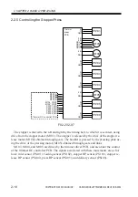
Page 48: ...05 obtained through gears and links M103 M104 and M105 are driven by the trimmer driver PCB and are under the control of the trimmer DC controller PCB The signals associated with these movements are as fol lows inlet sensor PS101 feeding sensor PS102 stopper HP sensor PS103 stopper re lease HP sensor PS104 press HP sensor PS105 and delivery sensor PS108 5V IN GND 24V 24V DRV A DRV A DRV B DRV B 24...

Page 49: ...e pressing plate locks the booklet in place The booklet is held in place until cutting ends at which time the booklet is released and the stopper is retuned to a specific position selected for each specific booklet size c Releasing the Press When the booklet has been cut M105 goes ON once again to release the booklet At the same time the stopper release motor M104 goes ON to start releasing the st...

Page 50: ...mer DC controller PCB it is a press assembly home position detection signal L at HP H not at HP 5 DRV trimmer DC controller PCB trimmer driver PCB M105 it is a drive signal for M105 L M105 ON H M105 OFF 6 M103 _A A trimmer DC controller PCB trimmer driver PCB M103 it is a phase A control signal for M103 7 M103_B B trimmer DC controller PCB trimmer driver PCB M103 it is a phase B control signal for...

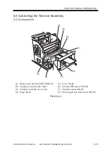
Page 51: ... 2 21 2 3 Controlling the Trimmer Assembly 2 3 1 Construction 1 Waste paper box full LED LED101 2 Trimmer assembly inlet roller 3 Trimmer assembly slave roller 4 Upper blade 5 Lower blade 6 Trimmer HP sensor PS106 7 Trimmer motor M102 8 Waste paper box full sensor PS109 F02 203 01 6 7 8 1 2 3 4 5 ...

Page 52: ...COPYRIGHT 2002 CANON INC 2000 CANON BOOKLET TRIMMER A1 REV 0 FEB 2002 CHAPTER 2 BASIC OPERATIONS 2 22 1 Waste paper removal fan motor M108 2 Waste paper box F02 203 02 1 2 ...

Page 53: ...lade moving up and down opposite the fixed lower blade The upper blade is driven by the trimmer motor M102 and is normally in up posi tion in wait in standby Items Description Feeding Trimmer assembly inlet roller Trimmer assembly slave roller Trim Upper blade reciprocating trimmer Waste paper removal Fan exhaust Waste paper box 1 Upper blade 2 Trimmer motor M102 3 Booklet 4 Lower blade F02 203 03...

Page 54: ...riven by the trimmer motor M102 Normally the upper blade is held in wait in up position and is monitored by the trimmer HP sensor PS106 at all times M102 is driven by the trimmer driver PCB and is controlled by the trimmer DC control ler PCB 1 Operation M102 starts to rotate clockwise as soon as pressing ends making a single up down trip causing the upper blade to move down to trim the booklet The...

Page 55: ... H not at HP 2 M102_CONT trimmer DC controller PCB trimmer driver PCB it is an ON OFF signal for M102 and M108 L M102 M108 ON H M102 M108 OFF 3 M102_F R trimmer DC controller PCB trimmer driver PCB it is a rotation direction switch signal for M102 L M102 CCW H M102 CW b Output signals 1 DRV trimmer driver PCB M102 it is a drive control signal for M102 The direction of drive current of two signals ...

Page 56: ...the trimmer driver PCB and is controlled by the trimmer DC control ler PCB The sensor associated with this operation is the waste paper box detection sensor PS107 1 Operation a Waste Paper Removal Fan M108 goes ON OFF in conjunction with the activation deactivation of M102 trimmer motor b Waste Paper Box When the waste paper box becomes full the optical path between LED101 and PS109 mounted to the...

Page 57: ...l L not full H full 3 LD M108 trimmer driver PCB it is an error detection signal for M108 When H an error is detected 4 SCAN OUT 1 2 trimmer DC controller PCB trimmer driver PCB it is a serial data line used to communicate the state of the machine to the trimmer DC controller PCB b Output Signals 1 GND trimmer driver PCB M108 it is a drive signal for M108 L M108 ON H M108 OFF 2 SCN IN1 2 trimmer d...

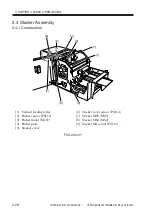
Page 58: ...BASIC OPERATIONS 2 28 2 4 Stacker Assembly 2 4 1 Construction 1 Vertical feeding roller 2 Pusher sensor PS112 3 Pusher motor M107 4 Pusher plate 5 Stacker cover 6 Stacker cover sensor PS114 7 Stacker MS3 MS3 8 Stacker MS4 MS4 9 Stacker full sensor PS113 F02 204 01 6 7 8 9 1 2 3 4 5 ...

Page 59: ...elivery sensor PS108 2 Holder upper limit sensor PS110 3 Timing belt 4 Holder motor M106 5 Holder lower limit sensor PS111 6 Holder plate F02 204 02 2 4 2 Mechanisms T02 204 01 6 1 2 3 4 5 Item Description Feeding Vertical feeding roller Delivery Holder plate Upright stack Deliver tray Constant load spring ...

Page 60: ...ght between the delivery tray and the holder plate in up position The booklet moved from the press assembly is delivered by the vertical feeding roller When the delivery sensor PS108 detects the passage of the trailing edge of the booklet the booklet is stopped and the holder plate is moved down a specific period of time thereafter by the work of the holder motor M106 A specific period of time the...

Page 61: ...ON BOOKLET TRIMMER A1 REV 0 FEB 2002 CHAPTER 2 BASIC OPERATIONS 2 31 1 Pusher motor M107 2 Pusher plate 3 Stacked booklets 4 Delivery tray 5 Holder plate 6 Constant load spring 7 Holder motor M106 8 Booklets F02 204 04 6 7 8 1 2 3 4 5 ...

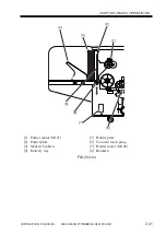
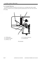
Page 62: ...pright Stacking The delivered booklet is held between the delivery tray and the pusher plate upright stacking The delivery tray is pushed against the pusher plate by the work of the constant load spring 1 Pusher plate 2 Stacked booklets 3 Delivery tray 4 Constant load spring 5 Holder plate F02 204 05 1 2 3 4 5 ...

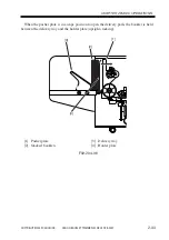
Page 63: ... CHAPTER 2 BASIC OPERATIONS 2 33 When the pusher plate is in escape position to open the delivery path the booklet is held between the delivery tray and the holder plate upright stacking 1 Pusher plate 2 Stacked booklets 3 Delivery tray 4 Holder plate F02 204 06 1 2 3 4 ...

Page 64: ...e driven by the trimmer driver PCB and are controller by the trimmer DC controller PCB The sensors associated with the operation are as follows inlet sensor PS101 delivery sensor PS108 upper limit sensor PS110 lower limit sensor PS111 pusher sensor PS112 stacker full sensor PS113 and stacker cover sensor PS114 5V IN GND 5V IN GND 5V IN GND 5V IN GND 5V IN GND 5V IN GND 5V IN GND DRV DRV DRV DRV M1...

Page 65: ...106 to push out the booklet delivered to the holder plate by the pusher plate in escape position to the delivery tray M106 start to rotate clockwise a specific period of time after the push plate ends its movement to move up the holder plate it goes OFF to end delivery when the upper limit sensor PS110 detects the upper limit of the holder plate 2 Through Mode The operation in through mode is the ...

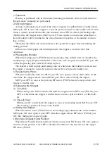
Page 66: ...imit H at lower limit 3 PS112_SIG PS112 trimmer driver PCB trimmer DC controller PCB it is a home position detection signal for the pusher plate L at HP H not at HP 4 IN PS113 trimmer driver PCB it is a stacker full detection signal L full H not full 5 M106 _CONT trimmer DC controller PCB trimmer driver PCB it is an ON OFF control signal for M106 L M106 ON H M106 OFF 6 M106_F R trimmer DC controll...

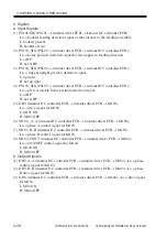
Page 67: ...drive control signal for M106 The direction of drive current of two signals is changed to control the direction of drive of M106 T02 204 02 2 DRV trimmer driver PCB M107 it is a drive control signal for M107 If the stacker cover is opened and the stacker MS3 MS3 is OFF the drive signal to M107 will be cut State DRV DRV Holder down H L Holder up L H Stop L L ...

Page 68: ...COPYRIGHT 2002 CANON INC 2000 CANON BOOKLET TRIMMER A1 REV 0 FEB 2002 CHAPTER 3 MECHANICAL SYSTEMS ...

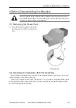
Page 69: ...otherwise instructed 0 1 Removing the Power Cord 1 Turn off the host machine and discon nect the power cord 1 from the trim mer F03 001 01 0 2 Checking the Operation After Re assembly Re assemble the trimmer body and turn on the trimmer and the copier then select trim mode trim ON to check the following Place 8 A4 originals in the copier and produce 3 or so booklets using the Booklet mode in the S...

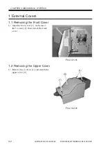
Page 70: ...2002 CHAPTER 3 MECHANICAL SYSTEMS 3 2 1 External Covers 1 1 Removing the Front Cover 1 Open the front cover 1 and remove the 5 screws 2 then detach the front cover F03 101 01 1 2 Removing the Upper Cover 1 Remove the 4 screws 1 and detach the upper cover 2 F03 102 01 ...

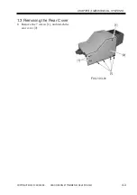
Page 71: ...COPYRIGHT 2002 CANON INC 2000 CANON BOOKLET TRIMMER A1 REV 0 FEB 2002 CHAPTER 3 MECHANICAL SYSTEMS 3 3 1 3 Removing the Rear Cover 1 Remove the 7 screws 1 and detach the rear cover 2 F03 103 01 ...

Page 72: ... CANON BOOKLET TRIMMER A1 REV 0 FEB 2002 CHAPTER 3 MECHANICAL SYSTEMS 3 4 1 4 Removing the Right Front Cover 2 1 Open the right front cover 1 1 and re move the 4 screws 2 then detach the right front cover 2 3 F03 104 01 F03 104 02 ...

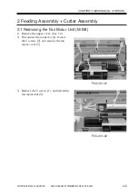
Page 73: ...ANICAL SYSTEMS 3 5 2 Feeding Assembly Cutter Assembly 2 1 Removing the Fan Motor Unit M108 1 Remove the upper cover See 1 2 2 Disconnect the connector 1 remove the 4 screws 2 and remove the fan motor cover 3 F03 201 01 3 Remove the 2 screws 1 and detach the fan motor unit 2 F03 201 02 ...

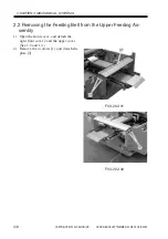
Page 74: ...B 2002 CHAPTER 3 MECHANICAL SYSTEMS 3 6 2 2 Removing the Feeding Belt from the Upper Feeding As sembly 1 Open the front cover and detach the right front cover 2 and the upper cover See 1 2 and 1 4 2 Remove the 4 screws 1 and detach the plate 2 F03 202 01 F03 202 02 ...

Page 75: ...ECHANICAL SYSTEMS 3 7 3 Remove the fan motor unit See 2 1 4 Remove the 3 screws 1 and detach the upper feeding assembly 2 F03 202 03 5 Remove the 3 screws 1 from the upper feeding assembly and detach the plate A 2 and the plate B 3 then detach the 2 upper feeding belts 4 F03 202 04 ...

Page 76: ...embly 1 Open the front cover and detach the right front cover 2 upper cover and rear cover See 1 2 through 1 4 2 Remove the upper feeding assembly See 2 2 3 Remove the 2 screws 1 and 2 and re move the stay 3 from the feeding as sembly likewise remove the 2 screws 4 and 5 and remove the stay 6 from the feeding assembly on the opposite side F03 203 01 F03 203 02 ...

Page 77: ... 0 FEB 2002 CHAPTER 3 MECHANICAL SYSTEMS 3 9 4 Remove the 4 screws 1 F03 203 03 5 Detach the belt 1 and remove the gear 2 and the E ring 3 F03 203 04 6 Remove the hex hole nut 1 and de tach the knob 2 then remove the E ring 3 and detach the shaft 4 F03 203 05 ...

Page 78: ... of the feeding belt B 3 F03 203 06 2 4 Removing the sensors at the Lower Feeding Assembly Waste Bin Full Sensor PS109 and Inlet Sensor PS101 1 Open the front cover and detach the right front cover 2 and the upper cover See 1 2 and 1 4 2 Perform steps 2 through 4 under 2 3 Removing the Feeding Belt from the Lower Feeding Assembly 3 Using the shaft 1 for support raise the lower feeding assembly 2 a...

Page 79: ...emove the screw 3 and detach the inlet sensor PS101 4 F03 204 02 2 5 Removing the Cutter Blade upper lower 1 Open the front cover and detach the right front cover 2 upper cover and rear cover See 1 2 through 1 4 2 Perform steps 2 through 4 under 2 2 Removing the Feeding Belt from the Upper Feeding Assembly 3 Remove the 3 screws 1 and detach the roller cover plate 2 F03 205 01 ...

Page 80: ...2 CHAPTER 3 MECHANICAL SYSTEMS 3 12 4 Free the cable 3 from the clip then remove the 4 screws 4 and detach the cutter cover plate 5 F03 205 02 5 Remove the E ring and the bushing 1 F03 205 03 6 Remove the E ring and the busing 1 and detach the upper roller 2 F03 205 04 ...

Page 81: ...late in place F03 205 05 8 Detach the 4 hex hole screws 1 then while picking the 2 knobs 2 detach the cutter upper blade 3 F03 205 06 9 Remove the 4 hex hole screws 1 and detach the cuter lower blade 2 1 The upper and lower blades of the cutter are extremely sharp Be sure to take extra care during the work 2 You will need a special tool to adjust the position of the cutter Do not remove any el eme...

Page 82: ...NC 2000 CANON BOOKLET TRIMMER A1 REV 0 FEB 2002 CHAPTER 3 MECHANICAL SYSTEMS 3 14 3 Control Panel 3 1 Removing the Trimmer ROM 1 Open the front cover and detach the up per cover See 1 2 2 Remove the trimmer ROM 1 F03 301 01 ...

Page 83: ...ANICAL SYSTEMS 3 15 3 2 Removing the Control Panel 1 Open the front cover and detach the right front cover 2 and the upper cover See 1 2 and 1 4 2 Remove the 4 screws 1 F03 302 01 3 Remove the 2 screws 1 and discon nect the 2 connectors 2 then free the cable 3 from the clip F03 302 02 ...

Page 84: ...PCB 1 Open the front cover and detach the up per cover See 1 2 2 Remove the screw 1 5 supports 2 and 5 connectors 3 and detach the Trimmer DC Controller PCB 4 In case the Trimmer DC Con troller PCB has been replaced with a new one VR1 adjustment LCD brightness adjustment and DSW3 setting must be com pleted See Chapter 5 for de tails F03 303 01 ...

Page 85: ...7 4 Stacker Assembly 4 1 Removing the Stacker Assembly 1 Remove the front cover right front cover 2 upper cover and rear cover See 1 1 through 1 4 2 Loosen the 6 screws 1 on the stacker bottom F03 401 01 3 Disconnect the 4 connectors 1 at the rear and pull out the cables through the opening 2 F03 401 02 ...

Page 86: ... CANON INC 2000 CANON BOOKLET TRIMMER A1 REV 0 FEB 2002 CHAPTER 3 MECHANICAL SYSTEMS 3 18 4 Detach the belt 1 F03 401 03 5 Remove the 3 screws 1 at the front F03 401 04 6 Remove the 3 screws 1 at the rear F03 401 05 ...

Page 87: ...ach the stacker assembly 1 while lifting it F03 401 06 4 2 Removing the Pusher Motor and the Pusher Sensor PS112 1 As in 4 1 remove the stacker assembly 2 Turn the gear 1 on the left of the pusher motor to match the positions of the screw 2 and the screw hole 3 then remove the screw through the hole F03 402 01 ...

Page 88: ...r 1 on the right side of the pusher motor to match the positions of the screw 2 and the screw hole 3 then remove the screw through the screw hole F03 402 02 4 Remove the 4 screws 1 and discon nect the 2 connectors 2 then detach the pusher motor F03 402 03 5 Remove the 4 claws 1 and detach the pusher sensor 2 F03 402 04 ...

Page 89: ...B 2002 CHAPTER 3 MECHANICAL SYSTEMS 3 21 6 Remove the E ring 1 and detach the gear 2 When mounting the gear be sure that the position of the gear hole 3 is correct on the left and the right F03 402 05 7 Remove the 2 screws 1 and detach the pusher motor 2 F03 402 06 ...

Page 90: ...rtical Feeding Roller Rubber 1 Remove the 4 screws 1 and detach the unit 2 Remove the E ring and the bushing 2 3 Remove the E ring gear and bushing 3 then remove the E ring gear pin E ring and bushing 4 Finally detach the roller unit 5 F03 403 01 F03 403 02 4 Remove the roller rubber 1 from each of the 3 rollers F03 403 03 ...

Page 91: ...ng the Stacker Cover Sensor PS114 and the Stacker Cover Switch MS3 MS4 1 Open the stacker cover and remove the 6 screws 1 then detach the cover 2 F03 404 01 2 Remove the 2 screws 1 and discon nect the 2 connectors 2 then detach the sensor unit 3 When mounting the unit be sure the actuator 4 is shifted up F03 404 02 ...

Page 92: ...3 MECHANICAL SYSTEMS 3 24 3 Disconnect the connector 1 and free the claw then detach the stack cover sensor PS114 2 Remove the 2 screws 3 and detach the stack cover switch MS3 MS4 4 MS3 and MS4 are used to turn ON OFF M107 push motor and M106 holder motor re spectively F03 404 03 ...

Page 93: ...AL SYSTEMS 3 25 5 Press Assembly 5 1 Removing the Upper Press Assembly 1 As shown in 3 2 remove the control panel 2 As shown in 4 1 remove the stacker as sembly 3 Remove the spring 1 F03 501 01 4 Through the screw hole remove the 2 screws 1 then detach the upper press assembly 2 F03 501 02 ...

Page 94: ... Press Assembly Feeding Belt 1 As shown in 5 1 remove the upper press assembly 2 Remove the 4 screws 1 and detach the plate 2 F03 502 01 3 Remove the 2 E rings 1 and detach the 2 feeding belt 2 F03 502 02 5 3 Removing the Lower Press Assembly 1 As shown in 5 1 remove the upper press assembly 2 Remove the 4 screws 1 F03 503 01 ...

Page 95: ... SYSTEMS 3 27 3 Remove the 3 screws 1 and detach the roller shaft cover 2 F03 503 02 4 Remove the E ring and bushing 1 used to keep the roller shaft in place F03 503 03 5 Remove the E ring gear pin E ring and busing 2 used to secure the shaft 1 in place in the lower press assembly F03 503 04 ...

Page 96: ...ower press assembly 1 F03 503 05 F03 503 06 If the trimming angle i e par allelism between the folding face and the trimming face of the booklet produced during testing after the trimmer body has been re assembled is not as indicated below make adjust ments as follows F03 503 07 Fold side Cut side A B Standard A B 1 mm ...

Page 97: ...d the Trimming Face 1 Open the front cover of the trimmer and loosen the 2 screws 1 F03 503 08 2 Open the feed guide pressure lever 1 and move the feed guide assembly 2 to the left or right with reference to the marking so that the angle is within the standard A single index of the marking equals a shift in the orthogonal angle of about 0 5 mm F03 503 09 1 1 2 ...

Page 98: ...or M103 1 As shown in 5 3 remove the lower press assembly 2 Remove the 2 screws 1 and detach the stopper motor M103 2 F03 504 01 5 5 Removing the Stopper Release Motor M104 1 As shown in 5 3 remove the lower press assembly 2 Remove the 2 screws 1 and discon nect the connector 2 then remove the stopper release motor M104 3 F03 505 01 ...

Page 99: ...r SP104 1 As shown in 5 3 remove the lower press assembly 2 Remove the feed sensor PS102 1 3 Remove the stopper HP sensor PS103 2 4 Remove the stopper release HP sensor PS104 3 F03 506 01 5 7 Removing the Lower Press Assembly Feeding Belt 1 As shown in 5 3 remove the lower press assembly 2 Remove the E ring and the 4 bushings 1 then remove the 2 shafts 2 and detach the 2 belts 3 F03 507 01 ...

Page 100: ...TEMS 3 32 5 8 Removing the Press Motor M105 1 As shown in 5 3 remove the lower press assembly 2 Shift the roller 1 as shown in the fig ure then remove the 4 screws 2 and detach the plate 3 F03 508 01 3 Remove the 2 screws 1 and discon nect the connector 2 then detach the press motor 3 F03 508 02 ...

Page 101: ...ou must make sure that the cutting operation of the trimmer has ended nor mally i e the phase of the cut ter motor must be in home posi tion so that the cutter motor may correctly be replaced Removing the Cutter Motor 1 As shown in 5 3 remove the lower press assembly 2 Remove the 5 screws 1 and discon nect the 2 connectors 2 then detach the cutter motor M102 3 F03 509 01 F03 509 02 ...

Page 102: ...tter mo tor to be mounted newly so that the cam hole 5 of the trimmer body is matched to the pin then mount the mo tor using 5 screws 1 Thereafter con nect the 2 connectors 2 If the grease on the drive pin of the cut ter motor to be mounted newly is not adequate be sure to apply an appropri ate amount of it before starting the mounting work F03 509 03 F03 509 04 ...

Page 103: ...00 CANON BOOKLET TRIMMER A1 REV 0 FEB 2002 CHAPTER 3 MECHANICAL SYSTEMS 3 35 5 10 Removing the Cutter HP Sensor PS106 1 As shown in 5 9 remove the cutter mo tor 2 Remove the 2 screws 1 and detach the cutter HP sensor 2 F03 510 01 ...

Page 104: ...R A1 REV 0 FEB 2002 CHAPTER 3 MECHANICAL SYSTEMS 3 36 6 Units at the Rear 6 1 Removing the Holder Motor M106 1 As shown in 1 3 remove the rear cover 2 Remove the 2 screws 1 and Discon nect the connector 2 then detach the holder motor M106 3 F03 601 01 ...

Page 105: ...per limit sensor PS110 4 Remove the 2 screws 5 and discon nect the connector 6 and remove the sensor holding plate lower 7 then detach the lower limit sensor PS111 8 You need to adjust the position when mounting the holder sen sor upper limit sensor or lower limit sensor perform either of the following two i Before removing the sensor mounting plate 3 4 mark its current position on the chassis usi...

Page 106: ...n using 2 screws Execute holder motor test in service mode to move the holder slide plate 9 to its upper limit For details see the section 2 5 in the ser vice mode chapter With the holder slide plate 9 at its upper limit adjust the position of the sensor mounting plate upper 3 so that the dis tance between the top edge of the upper sensor and the top edge of the slide plate is 10 1 mm then tightly...

Page 107: ...te 9 to its lower limit For details see the section 2 5 in the ser vice mode chapter With the holder slide plate 9 at its lower limit open the stacker cover and insert a screwdriver or the like through the detection slit 10 of the stacker cover sensor to keep it in place Adjust the position of the sensor mount ing plate lower 7 so that the distance be tween each top edge of the delivery guide and ...

Page 108: ...ve the rear cover 2 Remove the 4 screws 1 disconnect the connector 2 and remove the support 3 then detach the feeding motor M101 4 F03 603 01 6 4 Removing the Waste Paper Bin Sensor PS107 1 As shown in 1 3 remove the rear cover 2 Remove the 2 screws 1 take out the plate 2 disconnect the connector 3 and free the claw then detach the waste bin sensor 4 F03 604 01 ...

Page 109: ...etach the trimmer drive PCB 3 If you have replaced the trim mer drive PCB be sure to adjust VR1 for sensitivity of detecting a waste case full condition for details see the descriptions on troubleshooting in Chapter 5 F03 605 01 6 6 Removing the Power Supply Circuit Unit 1 As shown in 1 3 remove the rear cover 2 Remove the 6 screws 1 disconnect the 4 connectors 2 and remove the 2 clamps 3 then det...

Page 110: ... 6 6 remove the power sup ply circuit unit 2 Remove the 2 screws 1 and discon nect the 4 connectors 2 then detach the current breaker 3 F03 607 01 1 Check to make sure that the rating of the current breaker to be mounted newly is 20 A 2 When mounting the current breaker be sure that the lever 1 is on the right side of the red test button 2 F03 607 02 ...

Page 111: ...3 MECHANICAL SYSTEMS 3 43 6 8 Removing the Sensor press assembly bottom plate 1 As shown in 1 3 remove the rear cover 2 Put your hand under the base plate of the trimmer and free the claw 1 of the sensor claw Detach the sensor 2 and disconnect the connector F03 608 01 F03 608 02 ...

Page 112: ...COPYRIGHT 2002 CANON INC 2000 CANON BOOKLET TRIMMER A1 REV 0 FEB 2002 CHAPTER 4 MAINTENANCE AND INSPECTION ...

Page 113: ...screwdriver isopropyl alcohol grease CK 0562 1 2 Periodically Replaced Parts 1 Cutter upper lower blade Replace it when it has been used 500 000 times of the cutting operation 1 3 Periodically Cleaned Inspected Parts For the following clean inspect every 200 000 times of the cutting operation external cover feeding belt roller area around waste case feed drive unit The details are as follows 1 Ext...

Page 114: ...KLET TRIMMER A1 REV 0 FEB 2002 CHAPTER 4 MAINTENANCE AND INSPECTION 4 2 2 Feeding Belt Roller While turning the jam removal knob 3 clean the feeding belt 4 and the feeding roller 5 6 using isopropyl al cohol F04 103 01 F04 103 02 F04 103 03 ...

Page 115: ... 4 MAINTENANCE AND INSPECTION 4 3 3 Area Around the Waste Case Clean it F04 103 04 4 Feeding Drive Unit Check the 3 feeding belts 8 for dam age or looseness Check the grease on the 2 gears 9 10 if not adequate ap ply an appropriate amount of grease CK 0562 F04 103 05 F04 103 06 ...

Page 116: ...COPYRIGHT 2002 CANON INC 2000 CANON BOOKLET TRIMMER A1 REV 0 FEB 2002 CHAPTER 5 TROUBLESHOOTING ...

Page 117: ...nsity of the control panel LCD Turn clockwise for a darker image turn counterclockwise for a lighter image DSW3 for factory use Check to make sure that all bits are in OFF position LED for factory use 1 2 Trimmer Drive PCB If you have replaced the trimmer drive PCB perform the following to adjust the sensitiv ity for the waste case full condition sensor F05 102 01 Turn VR1 fully counterclockwise t...

Page 118: ...cessary For details see 5 3 of Chapter 3 1 4 Holder Upper Limit Sensor and the Holder Lower Limit Sensor If you have replaced the holder upper limit sensor or the holder lower limit sensor adjust its position when mounting it back into place For details see 6 2 of Chapter 3 1 5 Belt Tension of the Holder Plate If you have removed the holder plate lift the plate 2 with a force of 1 500 100 g using ...

Page 119: ...HT 2002 CANON INC 2000 CANON BOOKLET TRIMMER A1 REV 0 FEB 2002 CHAPTER 5 TROUBLESHOOTING 5 3 2 Upgrading the Software The software is upgraded when the trimmer ROM is replaced for details see 3 1 of Chapter 3 ...

Page 120: ...s not go ON within a specific period of time 3 sec when it is moved to cutter HP by rotating the cut ter motor in the backward direction 4 The fan motor rotation speed lock signal cannot be detected when the cutter motor is driven Action to take 1 Turn off and on the trimmer i e disconnect and connect the power cable 2 Turn off and on the host machine 3 Execute trim motor test in service mode to c...

Page 121: ...connect and connect the power cable 2 Turn off and on the host machine 3 Execute holder motor test in service mode to check the operation 4 Check the contact between the trimmer drive PCB connector CN401 and the trimmer DC controller PCB connector J1 if needed replace the harness 5 Check the contact of the holder motor relay harness connected to the trimmer drive PCB connector CN405 if needed repl...

Page 122: ...ion to take 1 Turn off and on the trimmer i e disconnect and connect the power cable 2 Turn on and off the host machine 3 Execute pusher motor test in service mode to check the operation 4 Check the contact between the trimmer drive PCB connector CN401 and the trimmer DC controller PCB connector J1 if needed replace the harness 5 Check the contact of the pusher motor relay harness connected to the...

Page 123: ... i e disconnect and connect the power cable 2 Turn on and off the host machine 3 Execute rear edge stopper motor test in service mode to check the op eration 4 Check the contact between the trimmer drive PCB connector CN401 and the trimmer DC controller PCB connector J1 if needed replace the harness 5 Check the contact of the rear edge stopper motor relay harness con nected to the trimmer drive PC...

Page 124: ... on the trimmer i e disconnect and connect the power cable 2 Turn off and on the host machine 3 Execute press motor test in service mode to check the operation 4 Check the contact of the harness between the trimmer drive PCB con nector CN401 and the DC controller PCB connector J1 if needed replace the harness 5 Check the contact of the press motor relay harness connected to the trim mer drive PCB ...

Page 125: ...in service mode to check the operation 4 Check the contact of the harness of the trimmer drive PCB connector CN401 and the trimmer DC controller PCB connector J1 if needed replace the harness 5 Check the contact of the feed motor relay harness connected to the trim mer drive PCB connector CN402 as needed replace the harness 6 Check the contact of the inlet sensor relay harness connected to the tri...

Page 126: ...urn off and on the trimmer i e disconnect and connect the power cable 2 Turn off and the on the host machine 3 Execute stopper release motor test in service mode to check the opera tion 4 Check the contact of the harness between the trimmer drive PCB con nector CN401 and the trimmer DC controller PCB connector J1 if needed replace the harness 5 Check the contact of the stopper release motor relay ...

Page 127: ... of detection No response signal from the trimmer is detected within a specific period of time 2 sec after the finisher sends a command to the trimmer detec tion on the finisher side Action to take 1 Turn off and on the trimmer i e disconnect and connector the power cable 2 Turn off and on the host machine 3 Check the connection between the trimmer DC controller PCB connec tor J5 and the finisher ...

Page 128: ...t sensor PS101 1 When the motor is initialized paper exists over the feed sensor PS102 2 When paper is moved paper exists over the feed sensor PS102 1 When the motor is initialized paper exists over the delivery sensor PS108 2 When paper is moved paper exists over the delivery sensor PS108 When power is turned on paper exits in any paper feed path While paper is moved a jam occurs when the front d...

Page 129: ...COPYRIGHT 2002 CANON INC 2000 CANON BOOKLET TRIMMER A1 REV 0 FEB 2002 CHAPTER 6 APPENDIX ...

Page 130: ...0 2 0 2 0 46 0 2 0 05 down up Set Release Press Release Pusher Release Press Pusher Set Stopper Set Stopper Release 0 2 0 46 0 2 0 476 0 05 down up 1st page starts Paper size position movement starts 2nd page starts unit second Case of Through Mode A3 16 sheets 2 copies Pusher Release Pusher Set 45 82 51 71 Stopper Set Stopper Release 0 2 0 46 0 2 down up Pusher Release Pusher Set Stopper Set Stop...

Page 131: ... 3 CN408 1 2 CN456 M 1 2 M102 CN407 1 2 2 1 1 2 CN412 CN412 CN412 M 3 2 1 1 2 3 M108 3 2 1 1 2 3 CN441 CN418 CN441 CN441 1 2 3 4 5 6 7 8 9 1 2 3 4 5 6 7 8 9 A10 B10 CN406A CN406B CN406 5V 5V 5V SUB_GND GND N C GND GND GND S G S G 5V 5V 5V 5V 5V 5V BKL CONT CLK PLL F R IN IN IN SUBIN 24V 24V P G P G N C P G GND P G 24V SUB_5V 5V IN IN IN IN GND GND GND GND 24V 24V DRVA DRV DRVA DRVB DRVB 24V 1 2 3 ...

Page 132: ...User Mode COPYRIGHT 2002 CANON INC 2000 CANON BOOKLET TRIMMER A1 REV 0 FEB 2002 ...

Page 133: ...user mode can be set on the host machine control panel or on the trimmer control panel respectively See the descriptions of service mode items System is selected as default display language switch over in user mode can be operated only on the trimmer control panel Trimmer Control Panel Operation Mode when System F00 101 01 Operation Mode when Local F00 101 02 Item screen General screen Menu Menu I...

Page 134: ...de is classified into the following 2 types F00 101 04 Initial screen Level 1 item screen Level 3 item screen Level 3 item screen Level 3 item screen General screen Select a Level 1 item Level 3 item screen Select an item Reset key Reset key OK TRIM ON Trim width adjust trimmer control panel host machine control panel trimmer control panel general screen Display language switch ...

Page 135: ...ust user mode screen see below will be indicated However if the operation mode is set to System this screen will not appear See the descriptions of service mode items F00 102 02 2 Press Menu once again so that a switch over will be made to display language switch user mode screen see below F00 102 03 3 For 1 and 2 press enter to start the user mode item in question Trim Error Enter Menu MENU TRIM ...

Page 136: ...ing Up the Data The following items related to user mode are backed up on the trimmer controller PCB trim width adjustment value trim width user adjustment value selected language REF If a discrepancy occurs in the nature of the backup the settings will return to default settings below trim width adjustment value 0 each size various adjustment values selected language Japanese Trim Error Enter Men...

Page 137: ...ervice mode items The following is the flow of work for trim TRIM width adjust 1 Press and select adjust clean on the display of the host machine control panel 2 Select trim TRIM width adjust 3 Select the paper for which to adjust the trim width 4 Enter an adjustment value Press C to clear the input value 5 Press OK to return to the Paper Selection screen 6 When all adjustments have been made pres...

Page 138: ...ng is the flow of work for trim width adjust F00 201 01 TRIM ON General screen Enter Enter Enter Paper size selection Menu User Mode screen Trim width adjustment adjusted by pressing or To User Mode screen MENU TRIM WIDTH ADJUST LTRR 00 0mm PAPER SIZE LTRR TRIM WIDTH 00 0mm PAPER SIZE A4R TRIM WIDTH 00 0mm PAPER SIZE B4 TRIM WIDTH 00 0mm PAPER SIZE A3 TRIM WIDTH 00 0mm PAPER SIZE 11x17 TRIM WIDTH ...

Page 139: ...it is 3 5 mm or more The following is the range of adjustment for trimming width A shift is made in the di rection of on the above figure the width may be any width greater than 3 5 mm T00 201 01 Factory setting 3 5 mm Reference point 0 mm Paper stack Trimming area Folding face Paper size mm 11 17 279 432 A3 297 420 B4 257 354 A4R 210 297 LTRR 216 279 Shift mm 3 4 to 10 2 9 5 to 10 2 10 3 to 10 2 ...

Page 140: ...he following is the flow of work for display language switch over under Menu F00 202 01 Enter TRIM ON General screen Enter Enter Language selection Menu User Mode screen Language selection To General screen MENU LANGUAGE SWITCH LANGUAGE SWITCH JAPANESE LANGUAGE SWITCH ENGLISH LANGUAGE SWITCH FRENCH LANGUAGE SWITCH GERMAN LANGUAGE SWITCH ITALIAN JAPANESE ENGLISH FRENCH GERMAN ITALIAN ...

Page 141: ...Service Mode COPYRIGHT 2002 CANON INC 2000 CANON BOOKLET TRIMMER A1 REV 0 FEB 2002 ...

Page 142: ...layer construction as shown User screen Item screen F00 101 01 The machine s service mode is divided into the following 6 types F00 101 02 Item screen Item screen Item screen General screen Preceding Next page Preceding Next page Menu 1 Version TRIM ON 2 Counter 3 Mode 4 Adjust Version indication general screen Trim counter Operation mode Trim width factory adjustment 5 Motor Motor test I O port i...

Page 143: ...Starting Service Mode and Making Selections F00 102 01 1 Press enter and enter in sequence so that the Service Mode screen will ap pear see below F00 102 02 2 Press to select the desired mode 1 3 Ending Service Mode Press Menu once to return to the User screen F00 102 01 Trim Error Enter Menu ...

Page 144: ...im width adjustment value trim width factory adjustment value selected language trimmer ON OFF REF If a discrepancy occurs in the contents of the back up the settings will re turn to the following default operation mode system trim counter 0 trim width adjustment value 0 each size each adjustment value selected language Japanese Trimmer ON While on a service visit do NOT change the setting of the ...

Page 145: ... 2000 CANON BOOKLET TRIMMER A1 REV 0 FEB 2002 SERVICE MODE S 4 2 Details of Items 2 1 Version Indication The following is the screen under 1 Version F00 201 01 1 Version Indicates the ROM version of the trimmer controller PCB ...

Page 146: ...or 2 Counter F00 202 01 2 Counter Indicates clears the number of times the trimmer unit has operated Indicating the Number of Operations The reading increases to 999 999 after which it will return to 0 CLEAR Clears the counter reading Enter Enter Enter Service Mode screen To Service Mode screen Clearing the counter reading to Service Mode screen ...

Page 147: ...de F00 203 01 3 Mode Selects trimmer operation mode Local Enables the use of the trimmer control panel for turning on off the trimming mechanism and adjusting the trim width System Enables the use of the host machine control panel for turning on off the trimming mechanism and adjusting the trim width Enter Enter Service Mode screen To Service Mode screen ...

Page 148: ...ve selected trim width factory setting the user adjustment value will be reset to 0 Enter Enter Enter Paper size selection Service Mode screen Trim width adjustment adjusted by pressing or To Service Mode screen SERVICE 4 Adjust LTRR 00 0mm PAPER SIZE LTRR TRIM WIDTH 00 0mm PAPER SIZE A4R TRIM WIDTH 00 0mm PAPER SIZE B4 TRIM WIDTH 00 0mm PAPER SIZE A3 TRIM WIDTH 00 0mm PAPER SIZE 11x17 TRIM WIDTH ...

Page 149: ...e 5 in total LTRR A4R B4 A3 11 17 paper will actually be moved in trim mode then adjustments will be made with reference to A and B F00 204 02 of a stack of sheets 2 sheets of plain paper i e so that the larger of the two will be in keep ing with the standard paper dimension 2 3 5 mm 0 5 mm For specifics of adjustment see F00 204 01 F00 204 02 The range of factory settings for trim width is as fol...

Page 150: ... width of the paper stack at its top and bottom F00 204 03 3 larger of the two 208 8 mm reference value 206 5 mm 2 3 mm thus enter 2 3 mm on the display control panel F00 204 01 F00 204 04 4 Feed paper once again in trim mode and measure the paper stack at its top and bottom to see that the larger of the two is 206 5 0 5 mm Otherwise make adjustments using the display control panel 208 8mm 208 6mm...

Page 151: ...rate as expected turn off the power without delay Do not use reverse rotation as part of the feed motor test F00 205 01 Enter Enter Enter SERVICE 5 Motor Feed M 000 1111110 00000000 Cutter M 000 1111110 00000000 RETURN 0 00000000 Stopper M 000 1111110 00000000 Release M 000 1111110 00000000 Press M 000 1111110 00000000 Holder M 000 1111110 00000000 Pusher M 000 1111110 00000000 Motor selection Ser...

Page 152: ...er release motor Press motor Holder motor Pusher motor Display operating Correct Forward Turn Over Reverse 100mm S 200mm S 300mm S 400mm S 500mm S 600mm S 700mm S RETURN end Correct Forward Turn Over Reverse RETURN end LTRR A4R B4 A3 11 17 Max Move maximum shift Home HP RETURN end Action shift to ON OFF position Action shift to ON OFF position Action shift to UP DOWN position Action shift to ON OF...

Page 153: ...xxxxx xx xxx xxxxxxx xxxx xxx xxx xxxxxxx xxx xxxx xxx xxxxxxx xx xxxxx xxx xxxxxxx x xxxxxx xxx xxxxxxx xxxxxxx xxx xxxxxx xxxxxxxx xxx xxxxx x xxxxxxxx xxx xxxx xx xxxxxxxx xxx xxx xxx xxxxxxxx xxx xx xxxx xxxxxxxx xxx x xxxxx xxxxxxxx xxx xxxxxx xxxxxxxx xx xxxxxxx xxxxxxxx x x xxxxxxx xxxxxxxx xx xxxxxxx xxxxxxxx No 0 1 2 3 4 5 6 7 8 9 10 11 12 13 14 15 16 17 I O port Feed lock sensor Cutter l...

Page 154: ...ON INC 2000 CANON BOOKLET TRIMMER A1 REV 0 FEB 2002 Prepared by Office Imaging Products Quality Assurance Center CANON INC Printed in U S A REVISION 0 FEB 2002 21767 5 1 Hakusan 7 chome Toride shi Ibaraki 302 8501 Japan ...

Page 155: ...PRINTED IN U S A IMPRIME AU U S A 0202ABX XX X This publication is printed on 100 recycled paper ...

Reviews:

Related manuals for Two-Knife Booklet Trimmer-A1