


COPYRIGHT © 2001 CANON INC. CLC1000/1000S/3100 REV.2 MAY 2001 PRINTED IN JAPAN (IMPRIME AU JAPON)
4-23
4. MECHANICAL SYSTEM
Figure 4-309A
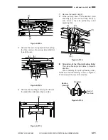
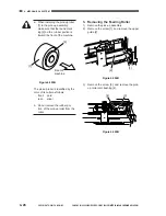
5)
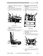
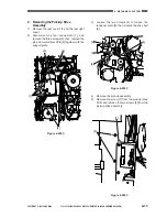
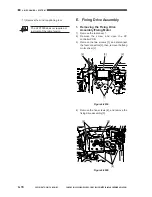
Remove the resin E-ring [4] and the bushing
[5]; then, remove the pick-up roller shaft [6]
toward the rear.
Figure 4-310A
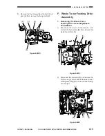
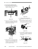
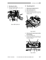
6)
Remove the mounting screw [7], and remove
the separation roller assembly cover [8].
Figure 4-311A
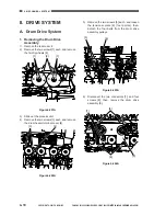
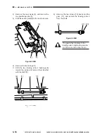
7)
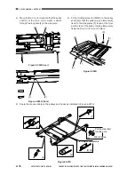
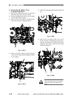
Remove the resin E-ring [9].
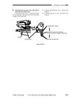
8)
While pushing down the separation roller
assembly [10], remove the timing belt [11],
and remove the pick-up/feeding roller
assembly [12].
[2]
[1]
[6]
[5]
[4]
[7]
[8]
Figure 4-312A
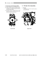
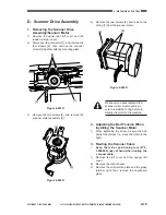
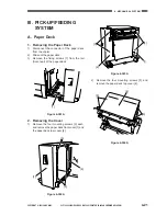
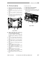
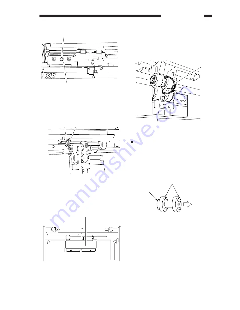
Orientation of the Pick-Up/Feeding Roller
The pick-up/feeding roller rotates in a specific
direction.
When installing the pick-up/feeding roller,
install it so that the marking shown in Figure 4-
313A is toward the rear of the machine.
Figure 4-313A
[9]
[10]
[11]
[12]
Markings
Bearing
(one-way)
Rear of
machine
Summary of Contents for Vizcam 1000
Page 12: ......
Page 30: ......
Page 44: ......
Page 86: ......
Page 254: ......
Page 372: ......
Page 374: ......
Page 418: ......
Page 438: ......
Page 442: ......
Page 754: ......
Page 764: ......
Page 766: ......
Page 840: ...0501GR PRINTED IN JAPAN IMPRIME AU JAPON This publication is printed on 100 reprocessed paper...