Chapter 6
6-3
Replace the cable between the operation panel and system controller if the connection is not functioning normally.
Replace the cable between the engine controller and power supply if the connection is not functioning normally.
Replace the cable between the power supply and inlet unit if the connection is not functioning normally.
5. Replace the power supply.
6. Replace the operation panel.
7. Replace the engine controller.
8. Replace the system controller.
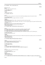
6.1.2.8 The power goes off during power on or while printing
0009-7131
<Condition example>
The power goes off during power on or while printing.
<Cause>
Printhead, carriage relay PCB, carriage unit
<Remedy>
1. Replace the printhead.
2. Replace the carriage relay PCB.
3. Replace the carriage unit.
4. Replace the engine controller.
5. Replace the system controller.
"Printhead Error! (E040000)" may appear when the power is turned off and then turned back on.
In this case, turn off the power once more and then start the printer in service mode.
Codes in parentheses are not displayed when a service call error occurs.
Service call errors can be check in the error history by selecting SERVICE MODE > DISPLAY > ERROR.
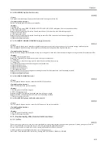
6.1.2.9 Network is not connected
0009-7069
<Condition example>
Printing cannot be performed from the network.
<Cause>
Cable is not connected properly, incompatibility with hub, system controller fault
<Remedy>
1. Check the cable.
Reconnect the LAN cable.
2. Check the communication settings.
Auto-negotiation cannot be performed for some configurations of the connected hub. Therefore, reset the network transmission speed and transfer mode
by matching each item of the [Ethernet Driver] in the [Interface Setting] menu with the specification of the hub that is used from the operation panel.
3. Replace the hub.
Explain to the customer that there is no problem with the printer unit.
4. Replace the sysytem controller.
6.1.2.10 Right cover does not open
0009-7071
<Condition example>
The right cover does not open. (No error message is shown on the display.)
<Cause>
Connector is not connected properly, engine controller fault
<Remedy>
1. Check the connector
Reconnect the right cover lock solenoid connector (J134) and right cover sensor (J82).
2. Replace the engine controller.
6.1.2.11 Printing problems (ink is full)
0009-7073
<Condition example>
Step 1
- Interface is not recognized.
- A test print can be printed, but printing from the host computer is not functioning normally.
Step 2
- No printing can be performed.
- Printing of the test print and printing from the host computer are not functioning normally.
- Textures appear in the image.
<Cause>
Faulty host computer, faulty interface cable, faulty expansion interface board, dirty carriage rail, improper position for head tilt lever, faulty printhead,
faulty purge unit, faulty linear scale, faulty carriage unit, faulty carriage relay PCB, faulty engine controller, faulty system controller
Step 1 remedy
1. Interface cable
Replace the interface cable if a visual check reveals that the connectors are damaged, deformed, or otherwise do not function normally.
Summary of Contents for WS8400
Page 1: ...Apr 5 2005 Service Manual W8400 Series W8400...
Page 2: ......
Page 6: ......
Page 12: ...Contents...
Page 13: ...Chapter 1 PRODUCT DESCRIPTION...
Page 14: ......
Page 16: ......
Page 21: ...Chapter 1 1 5 F 1 9...
Page 47: ...Chapter 2 TECHNICAL REFERENCE...
Page 48: ......
Page 91: ...Chapter 3 INSTALLATION...
Page 92: ......
Page 94: ......
Page 97: ...Chapter 4 DISASSEMBLY REASSEMBLY...
Page 98: ......
Page 100: ......
Page 138: ......
Page 139: ...Chapter 5 MAINTENANCE...
Page 140: ......
Page 142: ......
Page 146: ......
Page 147: ...Chapter 6 TROUBLESHOOTING...
Page 148: ......
Page 193: ...Chapter 6 6 43 F 6 8 Cover switch tool Cover switch tool...
Page 194: ......
Page 195: ...Chapter 7 SERVICE MODE...
Page 196: ......
Page 198: ......
Page 212: ......
Page 213: ...Chapter 8 ERROR CODE...
Page 214: ......
Page 216: ......
Page 222: ......
Page 223: ...Apr 5 2005...
Page 224: ......

