Chapter 1
1-25
F-1-25
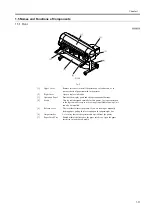
1.7.1.3 Electrical Parts
0009-1216
The electrical unit of the printer is activated when connected to the AC power supply.
At the rear of the printer are the system controller, engine controller, power supply, motor driver PCB, interface connector, and optional Take-up Unit
connector. The head relay PCB and carriage relay PCB are incorporated in the carriage unit, and the operation panel is located on the upper right cover.
When servicing the printer with the cover removed, be extremely careful to avoid electric shock and shorting contacts.
T-1-12
[1]
Operation panel
[6]
Engine controller
[2]
Carriage relay PCB
[7]
System controller
[3]
AC inlet
[8]
Interface connector
[4]
Power supply
[9]
Take-up unit connector
[5]
Motor driver PCB
[2]
[3]
[1]
Summary of Contents for WS8400
Page 1: ...Apr 5 2005 Service Manual W8400 Series W8400...
Page 2: ......
Page 6: ......
Page 12: ...Contents...
Page 13: ...Chapter 1 PRODUCT DESCRIPTION...
Page 14: ......
Page 16: ......
Page 21: ...Chapter 1 1 5 F 1 9...
Page 47: ...Chapter 2 TECHNICAL REFERENCE...
Page 48: ......
Page 91: ...Chapter 3 INSTALLATION...
Page 92: ......
Page 94: ......
Page 97: ...Chapter 4 DISASSEMBLY REASSEMBLY...
Page 98: ......
Page 100: ......
Page 138: ......
Page 139: ...Chapter 5 MAINTENANCE...
Page 140: ......
Page 142: ......
Page 146: ......
Page 147: ...Chapter 6 TROUBLESHOOTING...
Page 148: ......
Page 193: ...Chapter 6 6 43 F 6 8 Cover switch tool Cover switch tool...
Page 194: ......
Page 195: ...Chapter 7 SERVICE MODE...
Page 196: ......
Page 198: ......
Page 212: ......
Page 213: ...Chapter 8 ERROR CODE...
Page 214: ......
Page 216: ......
Page 222: ......
Page 223: ...Apr 5 2005...
Page 224: ......


