background image

Chapter 4  

4-34

4.4 Applying the Grease

4.4.1 Applying the Grease

0009-4822

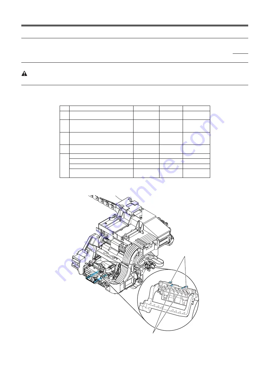
Apply the grease at the location shown below.

Smear the grease lightly and evenly with a flat brush.

Don't apply the grease to locations other than those designated. Unwanted grease may cause poor print quality, take particular care that grease does not get

onto the wiper, cap, or the linear scale.

T-4-1

F-4-72

No.

Place

Kind

Quantity

Note

1

The joint unit rail [1] and rib [2] of a carriage

Molykote PG-641 Smear the grease 

lightly

2

Two feed roller backup [1]

Permalub G No.2 approx.12mg

Don't apply to 
central backup with 
bearing.

3

Feed roller bearing [2]

Permalub G No.2 approx.24mg

Apply if remove 
bearing from a feed 
roller.

4

Pinch roller release cam three points[1] X 10 
parts

Permalub G No.2 Smear the grease 

lightly

5

Upper cover stay shaft hole [1]

Permalub G No.2 approx.24mg

The shaft [2] of the upper cover stay gear

Permalub G No.2 approx.24mg

Upper cover stay shaft end [3]

Permalub G No.2 approx.24mg

The tooth face [4] of an upper cover stay gear

Permalub G No.2 Smear the grease 

lightly

[2]

[1]

1.The joint unit rail [1] and rib [2] of a carriage

Summary of Contents for WS8400

Page 1: ...Apr 5 2005 Service Manual W8400 Series W8400...

Page 2: ......

Page 3: ...need arises In the event of major changes in the contents of this manual over a long or short period Canon will issue a new edition of this manual The following paragraph does not apply to any countri...

Page 4: ...uiring care to avoid combustion fire Indicates an item prohibiting disassembly to avoid electric shocks or problems Indicates an item requiring disconnection of the power plug from the electric outlet...

Page 5: ...ed to indicate Low The voltage value however differs from circuit to circuit In addition the asterisk as in DRMD indicates that the DRMD signal goes on when 0 In practically all cases the internal mec...

Page 6: ......

Page 7: ...15 1 6 2 Change of Printer Status 1 16 1 6 3 Main Menu 1 16 1 7 Safety and Precautions 1 23 1 7 1 Safety Precautions 1 23 1 7 1 1 Moving Parts 1 23 1 7 1 2 Ink 1 23 1 7 1 3 Electrical Parts 1 25 1 7...

Page 8: ...troller components 2 30 2 4 3 Engine Controller 2 31 2 4 3 1 Engine controller components 2 31 2 4 4 Carriage Relay PCB 2 32 2 4 4 1 Carriage relay PCB components 2 32 2 4 5 Head Relay PCB 2 33 2 4 5...

Page 9: ...nsumables 5 2 5 2 1 Consumables 5 2 5 3 Regular Maintenance 5 3 5 3 1 Regular Maintenance 5 3 Chapter 6 TROUBLESHOOTING 6 1 Troubleshooting 6 1 6 1 1 Outline 6 1 6 1 1 1 Outline of Troubleshooting 6 1...

Page 10: ...823 E02824 Adjustment error 6 10 6 1 4 20 E02B04 Upper cover sensor error 6 10 6 1 4 21 E02B05 E02B07 Right cover sensor error 6 10 6 1 4 22 E02B06 Carriage cover sensor error 6 10 6 1 4 23 E02B08 Pap...

Page 11: ...rvice Mode 7 5 7 2 Special Mode 7 13 7 2 1 Printer Special Mode 7 13 Chapter 8 ERROR CODE 8 1 Outline 8 1 8 1 1 Outline 8 1 8 2 Warning Table 8 2 8 2 1 Warnings 8 2 8 3 Error Table 8 3 8 3 1 Errors 8...

Page 12: ...Contents...

Page 13: ...Chapter 1 PRODUCT DESCRIPTION...

Page 14: ......

Page 15: ...3 Carriage 1 13 1 5 4 Internal part 1 13 1 6 Basic Operation 1 15 1 6 1 Operation Panel 1 15 1 6 2 Change of Printer Status 1 16 1 6 3 Main Menu 1 16 1 7 Safety and Precautions 1 23 1 7 1 Safety Prec...

Page 16: ......

Page 17: ...xternal View of Printer 1 2 F 1 1 T 1 1 1 The Network board is installed as a standard item for USA model External View of Printer 2 2 1 Right cover 7 Upper cover 2 Upper right cover 8 USB port 3 Oper...

Page 18: ...2 F 1 2 T 1 2 12 Ink tank 17 Belt stopper 13 Print head 18 Snag prevention stay 14 Roll holder 19 Cleaner brush 15 Holder stopper 20 Accessory pocket 16 Hex key wrench 21 Poewr cord 16 12 17 18 15 13...

Page 19: ...for 10Base T 100Base TX TCP IP network or IEEE1394 1 2 2 Printhead 0009 1059 On the carriage disposable printhead is installed each of which contains six rows of integrated nozzles Each row consists...

Page 20: ...6 inch 150 mm F 1 6 1 2 6 Consumables 0009 1139 Printhead This consumable printhead is the same as the printhead shipped with the printer F 1 7 Ink tank Seven types of consumable ink tank are availabl...

Page 21: ...Chapter 1 1 5 F 1 9...

Page 22: ...e top 5 mm from the bottom and 5 mm from the left and right edges Printable area may depend on the media Printable area Cut sheet Area excluding 5 mm from the top 23 mm from the bottom and 5 mm from t...

Page 23: ...release lever position detection Yes Roll media trailing edge detection Yes Remaining roll media detection Yes Feed roller rotation detection Yes Operating noise During printing Approx 54dB A max 6 9B...

Page 24: ...per Art Fine Art Photo Fine Art Heavyweight Photo Fine Art Textured Canvas Matte Canvas Semi Glossy Japanese Paper Washi Japanese Paper Washi Coated Paper Coated Paper Heavy Coated Paper Extra Heavywe...

Page 25: ...dpi Approx 3 0 min Coated Paper Heavy Coated Paper Extra Heavy Coated Paper Draft 4 pass 1200x1200dpi Approx 2 0 min Standard 6 pass 1200x1200dpi Approx 3 0 min High 8 pass 2400x1200dpi Approx 6 7 min...

Page 26: ...94a Version 2 0 standards 5 Interface connector Printer side IEEE1394 standards 6 pin connector socket Cable side IEEE1394 standards 6 pin connector plug c Network option except for USA model 1 Interf...

Page 27: ...4 Stand This is a table designed specially for this printer Casters are attached to the legs to make it easy to move An optional Media Take up Unit can also be installed 5 Release Lever The lever tha...

Page 28: ...pansion Board Slots Provided for installing a network interface board or IEEE1394 expansion board 4 USB Port This is the communication port for USB High Speed 2 0 Connect the USB cable here to connect...

Page 29: ...open the print head cover 4 Cutter Blade The cutter unit that cuts print media automatically 5 Print Head Height Adjustment Lever Use to adjust the height of the printhead You will need to adjust the...

Page 30: ...Chapter 1 1 14 T 1 8 1 Maintenance Cartridge The cartridge that vacuums and collects excess ink Replace the maintenance cartridge when a message appears prompting you to replace the cartridge...

Page 31: ...n a menu is displayed This button is used to return to the next higher level menu 6 button Offline status Holding down this button for 1 second or longer moves the carriage to the center of platen Whe...

Page 32: ...rameter settings 1 Main menu operations a How to enter the Main Menu To enter the Main menu press the printer s Online button several times b How to exit the Main Menu Press the Online button once to...

Page 33: ...nu Med Detail Set Plain Paper YES NO Printing adjustment menu Adjust Printer Interface setup menu Interface Setup YES NO YES NO System setup menu System Setup Information menu Information Head Cleanin...

Page 34: ...ear CutDustReduct Cut Speed Standard Cutter VacuumStrngth Media Thickness Far End RllMrgn NearEnd RllMrgn Scan Wait Time Off 30 seconds 1 min 3 5 10 30 min 60 min Off 1 sec 3 5 7 sec 9 sec Thick Stand...

Page 35: ...yed when Band Joint is selected for Feed Priority 2 Displayed when Print Length is selected for Feed Priority Adjust Printer Printhead Adj Color Calib Adjust Length 2 Adjust Band 1 Feed Priority Advan...

Page 36: ...ode On Off BOOTP On Off RARP On Off 0 255 0 255 0 255 0 255 Bindary Pserver RPrinter Off On Ethernet2 Ethernet802 2 Ethernet802 3 EthernetSNAP NDSPserver Nprinter Interface Setup EOP Timer NetWare 1 T...

Page 37: ...Off On Off Default values are underlined 1 Displays a screen to check whether to issue a Media type mismatch W01021 or whether the media is replaced On Off English Espanol No Yes System Setup Warning...

Page 38: ...unter Job Log Error Log MAC Address 1 Ext Interface RAM Document Name Coverage User Name Page Count Job Status Print Start Time Print End Time Print Time Print Size Media Type Interface Job Log 1 Job...

Page 39: ...open If the upper cover is opened in the online offline mode the carriage motor feed motor and other driving power supplies are turned off T 1 9 F 1 23 1 7 1 2 Ink 0009 1214 1 Ink passages Be careful...

Page 40: ...cerine 56 81 5 Ethylene glycol 107 21 1 Heterocyclic compound Copper compound Yellow ink Glycerine 56 81 5 Glycol Lactum Since this ink contains pigment stains will not come out of clothing 2 Ink mist...

Page 41: ...tional Take up Unit connector The head relay PCB and carriage relay PCB are incorporated in the carriage unit and the operation panel is located on the upper right cover When servicing the printer wit...

Page 42: ...n matter or dried ink install the printhead immediately after you remove the protective cap Also make sure to press down the locking lever of the printhead until you feel a click In addition to preven...

Page 43: ...wipe clean with a soft well wrung damp cloth If ink leaks onto electrical units wipe them completely using tissue paper In particular if ink penetrates beneath the IC chips on the logic board and you...

Page 44: ...ices In particular never touch the printhead contacts 1 F 1 29 2 Fixing the carriage After printing the carriage caps the printhead and uses the lock arm inside the purge unit to apply a mechanical lo...

Page 45: ...nk tank replacements carriage driving time number of cleanings and the cutter usage and stores this information in the system controller EEPROM IC10 and in the engine controller EEPROM IC28 as the ser...

Page 46: ...rge can damage electrical devices To prevent this discharge any static buildup by touching a grounded metal fitting before you start disassembling the printer 1 7 3 4 Precautions for Disassembly Reass...

Page 47: ...Chapter 2 TECHNICAL REFERENCE...

Page 48: ......

Page 49: ...ucture of carriage 2 12 2 3 2 4 Printhead 2 13 2 3 2 4 1 Structure of printhead 2 13 2 3 2 5 Purge Unit 2 14 2 3 2 5 1 Functions of purge unit 2 14 2 3 2 5 2 Structure of purge unit 2 16 2 3 2 6 Maint...

Page 50: ...ponents 2 33 2 4 6 Motor Driver 2 34 2 4 6 1 Motor driver PCB components 2 34 2 4 7 Power Supply 2 35 2 4 7 1 Power supply block diagram 2 35 2 5 Detection Functions Based on Sensors 2 36 2 5 1 Sensor...

Page 51: ...Ink tank unit Tank reley PCB Tank sensor Bk Tank sensor PC Tank sensor C Tank sensor PM Tank sensor M Tank sensor Y FT J84 J105 J6 Option cutter unit Cutter right switch Cutter left switch Cutter moto...

Page 52: ...in coordination with the discharge timing The ASIC also sends the command data from the system controller to the CPU f The CPU in the engine controller obtains the mask pattern data from the FLASH ROM...

Page 53: ...s signals are applied to adjust the pulse width according to the head rank head temperature internal temperature and other factors to ensure optimal ink discharge and then the heat board in the printh...

Page 54: ...dpi E_DATABK1 E_DATABK2 Low active Low active Linear scale Data of block 0 Data of block 0 Data of block 0 Data of block 0 Data of block 2 Data of block 2 Data of block 2 Data of block 2 Data of block...

Page 55: ...ers the online state and then press the power button to turn off the power 1 Power Off sequence Device resource initialization initialization Engine status check Cleaning No media Media detected Media...

Page 56: ...on under Print Quality settings in the printer driver The printer operation in standard mode depends on the printer driver sheet setting When printing in 6 pass bi directional format the image data is...

Page 57: ...aper Proofing Paper 1 Newspaper Proofing Paper 2 Newspaper Proofing Paper 3 1200x1200 600 6 Bi directional Plain paper CAD Tracing paper CAD Translucent Matte Film CAD CAD clear film 1200x1200 300 8 B...

Page 58: ...ects a temperature above 80 deg C 1 the printer allows the carriage to continue in the direction of its scanning pass and then stops it at the scan end position The wait control is activated to allow...

Page 59: ...d performs two types of paper feeding transport and discharge of media This section presents an overview of the components of the mechanical system F 2 7 2 3 2 Ink Passage 2 3 2 1 Ink Passage 2 3 2 1...

Page 60: ...ink tank is not installed ink supply valve is opened and printhead lock lever is opened when ink fills the ink tube the ink in the ink tube may reverse flow due to the difference in the water head an...

Page 61: ...rate ink supply valve is provided for black ink to allow the ink tank to be changed between Black and Matte Black F 2 10 2 3 2 3 Carriage Unit 2 3 2 3 1 Carriage functions 0009 1511 a Printhead mounti...

Page 62: ...transmission of print signals Also the ink passage from the ink tank passes through the ink tube and connects to the printhead b Ink port Ink passes through the ink tube and is supplied to the printhe...

Page 63: ...t lever is performed by print head position H sensor H L g Registration sensor unit The resistration sensor at left bottom of the carriage consists of two LEDs and receiver sensor h Rail cleaner unit...

Page 64: ...uction operation and when switching to the standby state due to an error The capping operation also connects the ink passage between the printhead and purge unit b Cleaning Cleaning includes a wiping...

Page 65: ...places the ink from Bk to MBk or from MBk to Bk Cleaning 13 Cleaning 14 Cleaning 15 Y dot count suction Performs suction to remove Y ink adhered due to nozzle drying Y ink accumulated on face when the...

Page 66: ...02g When Head Cleaning menu is selected Manual cleaning Head Cleaning A Cleaning 1 normal cleaning Approx 1g Manual cleaning Head Cleaning B Cleaning 6 normal strong cleaning Approx 6g When Replace P...

Page 67: ...e which is positioned perpendicular to the printhead wipes the entire face plate of the printhead and then the narrow blade is used to wipe the nozzle array After wiping the wiper blades are cleaned b...

Page 68: ...carriage on the purge unit The up down movement timing is detected by the PG position H sensor and the rotation is controlled by the pump motor stepping motor F 2 19 d Sensors Sensors are located in t...

Page 69: ...mediately The printer will not operate unless the maintenance cartridge is replaced with a new one MEMO This printer has an EEPROM in the maintenance cartridge and the maintenance cartridge status is...

Page 70: ...nch roller drive unit for pressing and releasing the pinch rollers and sensors for detecting the media feeding status The paper path performs manual feeding transport and delivery for the roll media a...

Page 71: ...carriage and move the registration sensor to media right edge detection start position 30mm inside the media right edge tentative detection position on media 7 Drive the carriage and detect the media...

Page 72: ...the carriage and move the registration sensor 30mm in the forward direction from the media left edge 10mm in the forward direction when in cutting dust reduction mode 10 Feed the media 50mm forward 1...

Page 73: ...ade cut disabled the position where the media should be cut is set as the leading edge of the media and roll media feeding is completed 4 Skew detection sequence The user can change the skew error det...

Page 74: ...Drive the carriage and move the registration sensor 30mm in the forward direction from the media right edge 2 Feed 300mm forward from the media set position 6 Media leading edge detection 1 Drive the...

Page 75: ...when detected 2 Feed the media backward and detect the media trailing edge with the media sensor stop feeding when detected 3 Registration sensor calibration 1 Move the registration sensor over the m...

Page 76: ...ps on the platen and a message is displayed when printing is finished MEMO When offline press the key to discharge the media and the key to rewind the media 2 3 3 2 Paper Path 2 3 3 2 1 Structure of f...

Page 77: ...t cutter When Autocut Yes is selected in the Printer Driver the cutter unit mounted on the left side of the carriage automatically cuts the roll media However the roll media is not cut if it is suppre...

Page 78: ...he left side of the printer automatically cuts the roll media Except when cutting roll media the cutter unit 2 is in standby at the cutter home position at the printer left side Once the roll media is...

Page 79: ...5 1Vgeneration function 26 5Vgeneration function AC inlet Optional connector assembly Print head Carriage unit Head relay PCB Temperature reading control function DI sensor reading control function S...

Page 80: ...enerator The CPU is connected to one 128MB DIMM board one 4MB ROM chips and one 8KB EEPROM chip The CPU has the following functions 1 DMA controller The DMA controller manages the USB expansion card s...

Page 81: ...trols communication with the system controller Image data reception Receives image data from the system controller stores in SDRAM IC15 IC16 and then converts to image data and stores in SDRAM IC11 IC...

Page 82: ...ta bus and is used as a CPU work memory g EEPROM IC28 The 32 Kbit EEPROM stores the printer adjustment values h Regulator IC IC25 The regulator IC generates the CPU and ASIC internal driving power sup...

Page 83: ...rol The environment temperature detected by the thermistor TH1101 on the head relay PCB is sent to the engine controller based on the control signals that are sent from the engine controller Relay for...

Page 84: ...d on the control signals from the engine controller c Pump motor driver IC4 IC5 This driver generates and sends the excitation signals for the pump motor based on the control signals from the engine c...

Page 85: ...y from the power supply and power button signals to control the STANDBY signals and turn the power on and off During power save mode the STANDBY signals are controlled to turn off the 26 5 V 5 1 V out...

Page 86: ...detects the opening and closing of the right cover When the right cover is closed the sensor light is cut off by the sensor arm and this notifies the sensor that the right cover is closed Pressure re...

Page 87: ...he homeposition of the pump is defined as the position where the rotary flag which operates in conjunction with the drive gear shaft of the rollers cuts off the sensor light F 2 40 Valve cam sensor Th...

Page 88: ...arrives at the location for detection it stops and the ink is discharged from one nozzle of the nozzle array at a time until all the nozzles are checked for their normal ink discharging operations Th...

Page 89: ...re sensor The environment temperature sensor thermistor installed on the head relay PCB detects the environment temperature in the vicinity of the carriage The resistance measured by the thermistor wh...

Page 90: ...ller home position sensor The feed roller home position sensor detects the change from white transparent to black opaque of the reference area of the scale on the code wheel when the power is turned o...

Page 91: ...Chapter 3 INSTALLATION...

Page 92: ......

Page 93: ...Contents Contents 3 1 Transporting the Printer 3 1 3 1 1 Transporting the Printer 3 1 3 1 1 1 Transporting The Printer 3 1 3 1 2 Reinstalling the Printer 3 2 3 1 2 1 Reinstalling the Printer 3 2...

Page 94: ......

Page 95: ...tand 7 Hold the printer carrying handle at the bottom and then slowly move the printer If the printer is subjected to strong vibrations when it is moved it can cause ink leakage or damage to the print...

Page 96: ...y and Precautions Other Precautions Handling the Printer Fixing the carriage 9 Close the upper cover 10 Attach the cushioning materials and tape 11 If the printer is mounted on a stand remove the prin...

Page 97: ...Chapter 4 DISASSEMBLY REASSEMBLY...

Page 98: ......

Page 99: ...8 Feeder unit 4 21 4 3 9 Purge unit 4 22 4 3 10 Ink tank unit 4 24 4 3 11 Head management sensor 4 26 4 3 12 PCBs 4 27 4 3 13 Opening the caps and moving the wiper unit 4 27 4 3 14 Opening and closin...

Page 100: ......

Page 101: ...boxes marked This side up and handle appropriately F 4 1 2 Feed roller The feed roller is a functionally important part Therefore be careful that the roller is not scratched or marked during storage o...

Page 102: ...inage in a dotted line performs manual or automatic either F 4 2 Symbol Meanings c Connector h claw s Screw Printer Automatic ink drainage Manual ink drainage L R circle cover L h1 L R circle cover S...

Page 103: ...Flexible cable c3 Print head Print head lock lever Spring Cable mount s2 Flexible cable c3 Carriage cover s5 Carriage unit Move the carriage unit over the platen Belt lock knob spring idler roller Pul...

Page 104: ...de cover s3 h1 Left side cover s3 h2 Right cover unit s4 Rear cover L s2 Upper rear cover s3 Upper cover Open the ink tank unit s1 Ink tank unit front cover s1 Upper left right cover h1 PCB cover s4 R...

Page 105: ...the operation panel for at least 0 5 seconds when the carriage is offline However when the power is turned off such as during assembly or disassembly move the carriage by holding the knobs 1 shown in...

Page 106: ...r to DISASSEMBLY REASSEMBLY Points to Notes on Disassembly and Reassembly Ink tube unit 3 Ink tank unit Refer to DISASSEMBLY REASSEMBLY Points to Notes on Disassembly and Reassembly Ink tank unit F 4...

Page 107: ...r backward F 4 11 b Left circle cover S right circle cover S Removing the left circle cover S right circle cover S Clicking the figure number under the video mark allows you to view the movie showing...

Page 108: ...Removing the right side cover Clicking the figure number under the video mark allows you to view the movie showing the procedure F 4 15 1 When removing the right side cover 1 remove the right circle...

Page 109: ...e the three screws 2 and two hooks 3 and then slide the left side cover to remove it F 4 18 e Operation panel Removing the operation panel Clicking the figure number under the video mark allows you to...

Page 110: ...eft upper right cover 1 remove the left right circle cover L left right circle cover S and left right side cover 2 Insert the flathead screwdriver at the position shown in the figure below and disenga...

Page 111: ...ews 2 2 When removing the rear cover right 3 remove the left cover left and then remove the two screws 4 F 4 24 h PCB cover Removing the PCB cover Clicking the figure number under the video mark allow...

Page 112: ...r the video mark allows you to view the movie showing the procedure F 4 29 1 When removing the upper rear cover remove the left right circle cover L left right circle cover S left right side cover upp...

Page 113: ...cover 2 While opening the left and right arm stays 1 one after another remove the upper cover 2 F 4 33 l Paper release lever Removing the paper release lever 1 When removing the paper release lever 1...

Page 114: ...the feed motor 1 F 4 35 b Action to take after replacing the feed roller home position sensor feed roller encoder or feed roller Eccentricity of the feed roller is factory corrected variation in the p...

Page 115: ...o Notes on Disassembly and Reassembly Draining the ink 2 Turn off the power and move the carriage over the platen If the carriage is fixed at the home position insert the flathead screwdriver in the s...

Page 116: ...t side joint in the ink supply base having an ink absorber 3 so that the joint is not disconnected accidentally 6 When ink has been drained automatically unlock the print head lock lever to allow the...

Page 117: ...4 17 F 4 41 9 Wrap the joint with a plastic bag or the like so that no ink splashes or leaks and then close the plastic bag F 4 42 10 Remove the two screws 1 and detach the cable mount 2 from the fra...

Page 118: ...mp securing the ink tube and remove the ink tube unit from the frame paying attention to ink splash and contact with the linear scale b Reassembling the ink tube unit After replacing the ink tube unit...

Page 119: ...3 Remove the print head 4 Remove the carriage cover For steps 11 and 12 refer to DISASSEMBLY REASSEMBLY Points to Notes on Disassembly and Reassembly Ink Tube Unit 5 Disconnect the flexible cable cabl...

Page 120: ...s not damage If the linear scale damages the printer can malfunction b Mounting the carriage belt Clicking the figure number under the video mark allows you to view the movie showing the procedure F 4...

Page 121: ...rriage unit or registration sensor adjustment is required Use the service mode under the following conditions Service mode SERVICE MODE ADJUST PRINT PATTERN OPTICAL AXIS Head height Low position Media...

Page 122: ...adjustment is required Use the service mode under the following conditions Service mode SERVICE MODE ADJUST PRINT PATTERN LF Carriage Low position Media type Glossy photo 4 3 9 Purge unit 0009 4807 a...

Page 123: ...Chapter 4 4 23 F 4 53 2 Remove the connector 6 and then remove the harness from the harness guide F 4 54 3 Remove the three screws 1 and then remove the purge unit 2 3 2 1 1 1...

Page 124: ...he ink For details refer to DISASSEMBLY REASSEMBLY Points to Notes on Disassembly and Reassembly Draining the ink 2 Remove the joint on the ink tube unit and ink tank unit 3 Place the ink tube unit si...

Page 125: ...4 25 F 4 57 b Removing the valve motor unit 1 When removing the upper valve motor unit remove the ink tank cover 2 Remove the three screws 1 and two connectors 2 and then remove the valve motor unit...

Page 126: ...connector 3 F 4 59 b Action to take after replacing the head management sensor Since the distance between the head management sensor and the carriage unit varies between printers the optical axis is f...

Page 127: ...button 7 Make sure that TURN OFF THE POWER appears on the display and then turn off the printer 8 Turn on the printer 9 Check the firmware version If the firmware version is not the latest update the...

Page 128: ...the movie showing the procedure F 4 63 1 Remove the right circle cover L right circle cover S and right side cover 2 From the right side of the printer insert the head of the Phillips screwdriver in...

Page 129: ...ply valve cam does not press the valve lever or the supply valve is closed If the tube is filled with ink and the print head lock lever is unlocked with the ink supply valve closed the ink in the tube...

Page 130: ...automatic ink drainage again 2 Manual ink drainage A syringe or other implement is used to remove the ink inside the ink passages one color at a time in the event of a printer electrical failure firm...

Page 131: ...cover unit Refer to DISASSEMBLY REASSEMBLY Points to Notes on Disassembly and Reassembly Outer covers 2 Remove the ink tank 3 Move the carriage over the platen Refer to DISASSEMBLY REASSEMBLY Points...

Page 132: ...and Reassembly Opening and closing the ink supply valve 8 Connect the syringe ink tube to the needle 2 of the ink supply side Pull the plunger of the syringe to remove the ink inside the ink supply u...

Page 133: ...Chapter 4 4 33 F 4 71 Ink tank unit 6 7 8 Carriage unit 5 Print head lock lever 5 Joint 4 5 Ink absorber 5 6 8...

Page 134: ...rriage Molykote PG 641 Smearthegrease lightly 2 Two feed roller backup 1 Permalub G No 2 approx 12mg Don t apply to centralbackupwith bearing 3 Feed roller bearing 2 Permalub G No 2 approx 24mg Apply...

Page 135: ...Chapter 4 4 35 F 4 73 F 4 74 1 2 2 Two feed roller backup 1 3 Feed roller bearing 2 1 4 Pinch roller release cam three points 1 X 10 parts...

Page 136: ...Chapter 4 4 36 F 4 75 1 2 4 3 5 Upper cover stay shaft hole 1 Gear shaft 2 Shaft end 3 Gear tooth face 4...

Page 137: ...istration sensor 0009 9500 Since the distance between the registration sensor in the carriage unit and the nozzle in the print head varies between printers the optical axis is factory adjusted to tune...

Page 138: ......

Page 139: ...Chapter 5 MAINTENANCE...

Page 140: ......

Page 141: ...Contents Contents 5 1 Regular Replacement Parts 5 1 5 1 1 Regular Replacement Parts 5 1 5 2 Consumables 5 2 5 2 1 Consumables 5 2 5 3 Regular Maintenance 5 3 5 3 1 Regular Maintenance 5 3...

Page 142: ......

Page 143: ...Chapter 5 5 1 5 1 Regular Replacement Parts 5 1 1 Regular Replacement Parts 0009 6209 T 5 1 Level Regular replacement part User None Service personnel None...

Page 144: ...umable User Printhead Ink tank black Ink tank matte black Ink tank photo cyan Ink tank cyan Ink tank photo magenta Ink tank magenta Ink tank yellow Cutter blade standard or option Maintenance cartridg...

Page 145: ...3 5 3 Regular Maintenance 5 3 1 Regular Maintenance 0009 6211 T 5 3 Level Regular maintenance User Cleaning of ink mist and other substances When necessary and when replacing the printhead Service per...

Page 146: ......

Page 147: ...Chapter 6 TROUBLESHOOTING...

Page 148: ......

Page 149: ...6 6 1 4 5 E02014 Cutter unit fuse failure error 6 7 6 1 4 6 E02015 Cutter error 6 7 6 1 4 7 E02400 E02401 E02402 E02403 Path mismatch error 6 7 6 1 4 8 E02405 E02406 E02407 Borderless printing error...

Page 150: ...or E04001 6 14 6 1 5 4 Scale read error E04002 6 14 6 1 5 5 Turn Power Off S04010 6 14 6 1 5 6 Turn Power Off E02777 6 14 6 2 Connector Positions and Pin Arrangement 6 15 6 2 1 System Controller 6 15...

Page 151: ...enomenon 6 1 2 1 Incorrect Value Check Value 0009 7061 Cause Invalid input value detected for Interface Setup TCP IP IP Setting IP Address Subnet Mask Default G W from the Main Menu Probable problem l...

Page 152: ...etween the head relay PCB and carriage relay PCB if the connection is not functioning normally 5 Replace the carriage relay PCB 6 Replace the carriage unit 7 Cable connection check Replace the cable b...

Page 153: ...ck the communication settings Auto negotiation cannot be performed for some configurations of the connected hub Therefore reset the network transmission speed and transfer mode by matching each item o...

Page 154: ...ulty ink tank unit faulty ink tube unit faulty engine controller faulty system controller Remedy 1 Visual check Remove the ink tube if it is bent or otherwise not functioning normally 2 Ink tank Remou...

Page 155: ...during manual feeding During back feeding the print standby position on feed roller is the feed limit During forward feeding the media sensor detects no roll media Probable problem locations Engine co...

Page 156: ...the registration sensor has detected a media larger than the prescribed size during media loading This is displayed when the registration sensor detects slanting that exceeds the prescribed amount du...

Page 157: ...ved data is designated for roll media This is displayed when the cut sheet is not loaded when the received data is designated for cut sheet This is displayed if the loaded media is roll media when the...

Page 158: ...g the Online button to start printing or pressing the Stop Eject button to cancel printing To cancel this error and recover the ink level detection function replace with a new ink tank designated for...

Page 159: ...A03 Engine controller internal error 0009 7107 Cause This is displayed when an error occurs in the engine controller EEPROM This is displayed when an error occurs in the firmware of the engine control...

Page 160: ...r sensor error 0009 7109 Cause This is displayed when the upper cover sensor L R has detected upper cover open status even though it is locked Probable problem locations Upper cover upper cover safety...

Page 161: ...connection is not functioning normally 5 Replace the engine controller 6 Replace the system controller 6 1 4 24 E02D00 E02D01 E02D0A E02D0B Sensor error in purge unit 0009 7113 Cause This is displayed...

Page 162: ...if there are any foreign objects adhering to the motor gears and sensors of the valve motor unit and remove if any abnormalities are found 2 Valve motor unit Check operation by using SERVICE MODE FUN...

Page 163: ...a visual check reveals slack in the carriage belt remount the belt 4 Replace the linear scale 5 Replace the linear encoder 6 Replace the carriage motor 7 Cable connection check Replace the cable betwe...

Page 164: ...the linear scale Probable problem locations Linear scale carriage sensor carriage relay PCB carriage unit engine controller system controller Remedy 1 Visual check Replace the linear scale if it is di...

Page 165: ...ring sleep mode 10 N C N C 11 GND GND 12 PME IN Power management enable signal 13 INTA IN Interrupt signal 14 GND GND 15 RST OUT Reset signal 16 CLK OUT Clock signal 17 GNT OUT Ground signal 18 GND GN...

Page 166: ...D15 IN OUT Address and data signal 58 AD14 IN OUT Address and data signal 59 AD13 IN OUT Address and data signal 60 AD12 IN OUT Address and data signal 61 GND GND 62 AD11 IN OUT Address and data signa...

Page 167: ...OUT Engine status acknowledge signal 15 ENABLE OUT Image data enable signal 16 GND GND 17 GND GND 18 GND GND 19 D1 IN OUT Parallel communication data signal 20 GND GND 21 D4 IN OUT Parallel communica...

Page 168: ...ta signal 66 GND GND 67 D12 IN OUT Parallel communication data signal 68 D14 IN OUT Parallel communication data signal 69 D15 IN OUT Parallel communication data signal 70 STANDBY OUT Software SW power...

Page 169: ...9 ENG_D1 IN OUT Bidirectional data bus bit1 20 GND GND 21 ENG_D4 IN OUT Bidirectional data bus bit4 22 ENG_D5 IN OUT Bidirectional data bus bit5 23 ENG_D7 IN OUT Bidirectional data bus bit7 24 GND GND...

Page 170: ...a bus bit9 66 GND GND 67 ENG_D12 IN OUT Bidirectional data bus bit12 68 ENG_D14 IN OUT Bidirectional data bus bit14 69 ENG_D15 IN OUT Bidirectional data bus bit15 70 STANDBY IN Power ON OFF signal 71...

Page 171: ...e jet CLMP signal 11 GND GND J107 Pin number Signal name IN OUT Function A1 3 3V OUT Power supply 3 3V A2 GND GND A3 ATUKAIJO IN Pressure release sensor detection signal A4 3 3V OUT Power supply 3 3V...

Page 172: ..._DIR OUT Feed motor rotation direction control signal A17 CR_DIR OUT Carriage motor rotation direction control signal A18 CR_BRAKE OUT Carriage motor brake signal A19 GND GND A20 5V OUT Power supply 5...

Page 173: ...IN OUT Function 1 GND GND 2 CUT UNIT IN Cutte unit detection siganal 3 CUT_L IN Cutter position detect signal left 4 CUT_R IN Cutter position detect signal right 5 CUTTER_D2 OUT Cutter motor drive sig...

Page 174: ...A_Y0_I2 OUT Even nozzle data 0 Y 40 GND GND 41 O_DATA_Y1_I2 OUT Even nozzle data 1 Y 42 GND GND 43 E_DATA_Y0_I2 OUT Odd nozzle data 0 Y 44 GND GND 45 E_DATA_Y1_I2 OUT Odd nozzle data 1 Y 46 GND GND 47...

Page 175: ...40 O_DATA_C0_I2 OUT Even nozzle data 0 C 41 GND GND 42 O_DATA_C1_I2 OUT Even nozzle data 1 C 43 GND GND 44 E_DATA_C0_I2 OUT Odd nozzle data 0 C 45 GND GND 46 E_DATA_C1_I2 OUT Odd nozzle data 1 C 47 GN...

Page 176: ...LK_O OUT LICC2 data clock 36 GND GND 37 LICC2_LD_O OUT LICC2 data latch signal 38 GND GND 39 LICC2_DT_O OUT LICC2 data L 40 GND GND 41 VHENB_O OUT Head drive voltage on off control signal 42 GND GND 4...

Page 177: ...citation signal B A16 INKM_M3_BX_N 1 OUT Valve motor phase excitation signal BN A17 PUMPM1_B OUT Pump motor phase excitation signal B A18 PUMPM3_BX_N1 OUT Pump motor phase excitation signal BN A19 CAP...

Page 178: ...ignal AN A5 24V OUT Power supply 26 5V A6 CAP1_A OUT Cap motor phase excitation signal A A7 CAP1_AN OUT Cap motor phase excitation signal B A8 CAP1_B OUT Cap motor phase excitation signal BN A9 CAP1_B...

Page 179: ...rial communication data siganl 13 GND GND 14 LICC2_LD_0 IN LICC2 serial communication LD 15 GND GND 16 LICC2_CLK_0 IN LICC2 serial communication clock 17 GND GND 18 3 3V IN Power supply 3 3V 19 GND GN...

Page 180: ...n data C1 6 GND GND 7 E_DATA_C0_I2 IN Even data C0 8 GND GND 9 O_DATA_C1_I2 IN Odd data C1 10 GND GND 11 O_DATA_C0_I2 IN Odd data C0 12 GND GND 13 E_DATA_M1_I2 IN Even data M1 14 GND GND 15 E_DATA_M0_...

Page 181: ...ion 1 GND GND 2 O_DATA_LM0 OUT LM even nozzle data 0 3 O_DATA_LM1 OUT LM even nozzle data 1 4 E_DATA_LM0 OUT LM odd nozzle data 0 5 E_DATA_LM1 OUT LM odd nozzle data 1 6 O_DATA_LC0 OUT LC even nozzle...

Page 182: ...BK C5_HENB_B OUT BK heat pulse output 13 GND GND 14 LICC2_CLK OUT LICC2 input data clock 15 GND GND 16 DSOUT2 IN LICC2 analog output 17 DSOUT1 IN LICC2 analog output 18 LICC2_LT OUT LICC2 input data l...

Page 183: ...HDCLKP_0 IN Head drive clock differential signal 3 HDCLKN_0 IN Head drive clock differential signal 4 GND GND 5 GND GND 6 E_DATA_Y1_I2 IN Even data Y 1 7 GND GND 8 E_DATA_Y0_I2 IN Even data Y 0 9 GND...

Page 184: ...rature monitor sigana2 48 NC NC 49 SNS_R_I OUT Registration sensor signal R 50 GND GND J1102 Pin number Signal name IN OUT Function 1 RGV19 OUT Power supply for driving head 2 RGV19 OUT Power supply f...

Page 185: ...ODATA0 OUT Even nozzle data 0 BK 40 C0_EDATA0 OUT Odd nozzle data 0 Y 41 DIAY0 IN DI sensor signal 0 Y 42 C1_ODATA1 OUT Even nozzle data 1 M 43 C0_EDATA1 OUT Odd nozzle data 1 Y 44 DIAM1 IN DI sensor...

Page 186: ...M1 IN M odd nozzle data 1 9 E_DATA_M0 IN M odd nozzle data 0 10 O_DATA_M1 IN M even nozzle data 1 11 O_DATA_M0 IN M even nozzle data 0 12 E_DATA_Y1 IN Y odd nozzle data 1 13 E_DATA_Y0 IN Y odd nozzle...

Page 187: ...ata latch signal 14 DSOUT1 OUT LICC2 analog output 15 DSOUT2 OUT LICC2 analog output 16 GND GND 17 LICC2_CLK IN LICC2 input data clock 18 GND GND 19 BK C5_HENB_B IN BK heat pulse output 20 LC C4_HENB_...

Page 188: ...N control signal 8 VM OUT Head power supply 9 VM OUT Head power supply 10 MGND GMD 11 MGND GND 12 Vcc2 OUT Power supply 5 1V 13 Vcc2 OUT Power supply 5 1V 14 GND GND 15 GND GND J1003 Pin number Signal...

Page 189: ...n nozzle 38 DIAY0 OUT DI sensor signal Y nozzle array 39 E_DTY1 IN Nozzle data signal Y nozzle array even nozzle 40 O_DTBK1 IN Nozzle data signal Bk nozzle array odd nozzle 41 E_DTBK1 IN Nozzle data s...

Page 190: ...PROM clock signal 73 EPDI IN Head EEPROM write data signal 74 DIAC1 OUT DI sensor signal C nozzle array 75 HE_C IN Heat enable signal C nozzle array 76 SHE_Y IN Sub heat enable signal Y nozzle array 7...

Page 191: ...can use the GARO Firmware Update Tool to update the versions of the firmware for the system controller installed in the printer The GARO Firmware Update Tool is the same as the one for the user For th...

Page 192: ...oving the spring parts Hex key wrench Inserting and removing hexagonal screws Penlight Assisting in the manual capping procedure Multimeter Troubleshooting Flat brush Applying grease Lint free paper W...

Page 193: ...Chapter 6 6 43 F 6 8 Cover switch tool Cover switch tool...

Page 194: ......

Page 195: ...Chapter 7 SERVICE MODE...

Page 196: ......

Page 197: ...Contents Contents 7 1 Service Mode 7 1 7 1 1 Service Mode Operation 7 1 7 1 2 Map of the Service Mode 7 1 7 1 3 Details of Service Mode 7 5 7 2 Special Mode 7 13 7 2 1 Printer Special Mode 7 13...

Page 198: ......

Page 199: ...x and Wxxxx are shown on the display by turning the power off and then using the above key operation b How to exit Service mode To exit Service mode turn off the printer c Buttons used in Service mode...

Page 200: ...R POWER ON W INK CUTTER PRINT PRINTCOUNT 3 CLN CLN A CLN M CLR INK CONSUME CLR CUTTER EXC CLR MTC EXC CLR HEAD EXC CLR PARTS 2 FACTORY CNT CARRIAGE PURGE CLEAR EXCHANGE LIFE CUTTER POWER ON 2 POWER ON...

Page 201: ...ECK PM MEDIACONFIG CNT INK USE1 BK INK USE 1 INK USE1 MBK INK USE1 C INK USE1 M INK USE1 Y INK USE1 PC INK USE1 PM INK USE1 TOTAL N INK USE1 BK N INK USE1 MBK N INK USE1 C N INK USE1 M N INK USE1 Y N...

Page 202: ...OOF SQ GLP COATED SQ GLP PLAIN SQ GLP SYN SQ GLP FILM SQ GLP CLOTH SQ GLP CAD SQ P SQ 44 MEDIASIZE1 P SQ 36 44 P SQ 24 36 P SQ 24 P CNT 44 P CNT 36 44 P CNT 24 36 P CNT 24 D SQ 44 MEDIASIZE2 D SQ 36 4...

Page 203: ...00000 07 W00000 08 W00000 09 W00000 10 W00000 11 W00000 12 W00000 13 W00000 14 W00000 15 W00000 16 W00000 17 W00000 18 W00000 19 W00000 20 W00000 ERROR 01 E02000 02 E02500 03 E02500 04 E02500 05 E0000...

Page 204: ...ion sensor optical axis It takes about 2 minutes to print this pattern For details refer to Disassembly Reassembly Adjustment and Setup Items Action to take after replacing the carriage unit or regist...

Page 205: ...ight and left fans rotate simultaneously for about 10 seconds PURGE This checks operation of the recovery system After the carriage is moved to the homeposition the recovery suction operation is perfo...

Page 206: ...N Number of automatic and manual cleanings times CLN A Number of automatic cleanings times CLN M Number of manual cleanings times Display Description Unit CLR INK CONSUME Cumulative ink sectional cons...

Page 207: ...f genuine ink ml INK USE1 C Cumulative consumption amount of genuine ink ml INK USE1 M Cumulative consumption amount of genuine ink ml INK USE1 Y Cumulative consumption amount of genuine ink ml INK US...

Page 208: ...xecute Ink Check Off in main menu total ml Display Description Unit INK EXC BK Cumulative genuine ink replacement count times INK EXC MBK Cumulative genuine ink replacement count times INK EXC C Cumul...

Page 209: ...paper smaller than 24 inches Actually outputted paper size m2 P CNT 44 Cumulative number of printed sheet 44 inches or more Actually outputted paper size m2 Cumulative number of printed sheet 36 to 4...

Page 210: ...n WARNING Initialization of DISPLAY WARNING ERROR Initialization of DISPLAY ERROR ADJUST Initialization of ADJUST W INK Initialization of COUNTER PRINTER W INK MIST COUNT Initialization of MIST COUNT...

Page 211: ...ce Mode 1 Controller Replace Mode This mode is used when replacing the system controller and engine controller This mode transfers the setting values counter values and other data before replacement i...

Page 212: ......

Page 213: ...Chapter 8 ERROR CODE...

Page 214: ......

Page 215: ...Contents Contents 8 1 Outline 8 1 8 1 1 Outline 8 1 8 2 Warning Table 8 2 8 2 1 Warnings 8 2 8 3 Error Table 8 3 8 3 1 Errors 8 3 8 4 Sevice Call Table 8 5 8 4 1 Service call error list 8 5...

Page 216: ......

Page 217: ...error display remains on the operation panel even if printer power goes off and on This is to avoid that the user can cleare service call errors preventing the printer from damage Service call errors...

Page 218: ...Mist Full Soon Waste ink in platen waste ink box and waste ink in mist fan unit are almost full W0100F Feed Limit Manual feed limit W01021 Incorrect Media Media type is not correct W01022 No full ble...

Page 219: ...s were not loaded even though the received data indicated cut sheets E02403 Media was too small during printing of adjustment pattern E02405 Invalid paper position for borderless printing E02406 Data...

Page 220: ...y improper adjustment E02823 Print head check error E02824 Optical axis improper adjustment E02A00 Engine controller internal error E02A01 E02A02 E02A03 E02B04 Upper cover was opened when upper cover...

Page 221: ...not shown on the display when service call error occurs T 8 4 Code 1 Display message Status E04000 Printhead Error Head voltage error E04001 Mist Count Error Waste ink in platen waste ink box and wast...

Page 222: ......

Page 223: ...Apr 5 2005...

Page 224: ......

Reviews: