background image

No. D17-7312

Digital Video Camera

CANON INC. 2003

Canon Inc.

Digital Imaging Products Service Dept.

First Edition : Feb. 2003

First Print : Feb. 2003

NTSC

Video Product

c

ZR70 MC A
ZR65 MC A

ZR60 A

ZR70 MC A
ZR65 MC A

ZR60 A

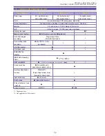
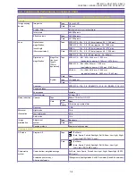
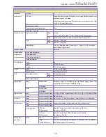
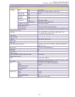
Summary of Contents for ZR70 MC A

Page 1: ... 7312 Digital Video Camera CANON INC 2003 Canon Inc Digital Imaging Products Service Dept First Edition Feb 2003 First Print Feb 2003 NTSC Video Product c ZR70 MC A ZR65 MC A ZR60 A ZR70 MC A ZR65 MC A ZR60 A ...

Page 2: ... Calling Up the Direct Print Setting Screen 1 13 3 Performance and Functions 1 14 4 System Diagram Common to all Models 1 24 5 Overview of Viewfinder LCD Panel Displays 1 25 5 1 Camera Mode 1 25 5 2 VCR Mode 1 32 5 3 Card Camera Mode ZR70 MC A ZR65 MC A only 1 36 5 4 Card Playback Mode ZR70 MC A ZR65 MC A only 1 39 5 5 Menu Display 1 41 5 6 Card Related Screen Displays 1 52 5 7 Direct Print Settin...

Page 3: ...Protection Signals 1 74 7 11 Video ID1 Detection Output Support 1 74 7 12 Audio Dubbing 1 75 7 12 1 Tapes to which Audio Dubbing can be Added 1 75 7 12 2 Selecting an Audio Dubbing Signal Input Source 1 75 7 12 3 Audio Dubbing Procedure 1 75 7 12 4 CGMS 1 75 7 13 AV Insert Not available on PAL Models 1 76 7 13 1 Tapes Allowing AV Insert 1 76 7 13 2 AV Insert Signal Input Source Selection 1 76 7 13...

Page 4: ...nts 1 2 Main Features 1 Compact Stylish New Stylish Design 2 High Performance Lens 22 optical zoom lens compatible with 1 6 inch CCD ZR70 MC A only 3 Excellent Picture Quality MACS system for improved picture quality 4 Multimedia Memory card slot USB terminal ZR70 MC A ZR65 MC A only Motion JPEG ZR70 MC A only Camera Direct Camera Direct 5 Advanced Specification Advanced accessory shoe ZR70 MC A o...

Page 5: ...ital video camcorders and PCs Allows bidirectional sending of audio or video content and messages text or images via the Internet Basic specifications are compatible with Windows Messenger Allows control camera zoom and focus VCR playback and stop access to the memory card of the digital video camcorder from a remote PC Control printer from DVC ZR70 MC ZR65 MC XGA size 1024 768 still images Direct...

Page 6: ...ixels LCD monitor EVF 0 33 inch screen 113 000 pixel color viewfinder Analog line input 2 Memory card function SD memory card MultiMediaCard Card Still images Progressive Photo recording 1024 768 640 480 Card motion video Motion JPEG audio recording monaural USB file transfer USB direct print IEEE1394 file transfer IEEE1394 streaming video USB compatible Accessory shoe Compatible with advanced acc...

Page 7: ...0 201 6 mm 1 008 mm equivalent to approx 3 888 mm 19 440 mm Card None System Tape CCD readout Card F number ZR70 MC A F1 6 3 6 ZR65 MC A F1 6 3 2 ZR60 A F1 6 2 9 Aperture blades 2 Zoom speed Variable Filter diameter 30 5mm P0 5 Noise reduction Camera Tape Either CCD NR or Y C NR Card None Chroma only median filter Recorder C NR Minimum Night mode 1 6 lx illumination Low Light mode 3 4 lx Auto mode...

Page 8: ...Outdoor Indoor System TTL 128 segments Focus Mode AF MF forced infinity Manual focus Multi switch operation 16 9 Recording system Tape Vertical Stretching Card Area marker display Digital fade Tape Motion video Auto Fade Wipe Corner Wipe Jump Flip Puzzle Zigzag Beam Tide executed by pressing the Start Stop button Still Image Card Motion video Still Image Digital effect Tape Motion video still Imag...

Page 9: ...ideo light For only ZR70 MC A white LED is provided turned ON in super night mode low light mode Zebra pattern Color bar display Selftimer 10 sec remote control 2 sec Interval timer Clear scan Recorded image size file format VGA 640 H 480 V XGA 1024 H 768 V JPEG ZR70 MC A ZR65 MC A only Memory card SD memory card MultiMediaCard REC search REC review Standby switch Power save after 5 minutes in Rec...

Page 10: ...oom Tape playback or card still image playback effects D effects Tape Art Black White Sepia Mosaic Ball Cube Wave Color Mask Mirror Card D fade Tape Auto fade Wipe Corner wipe Jump Flip Puzzle Zig Zag Beam Tide Card Multi screen 4 9 16 screen tape only Data code display Time and Date display Card Slide show ZR70 MC A ZR65 MC A only Index playback ZR70 MC A ZR65 MC A only 6 screen playback Card fas...

Page 11: ...ct print When connected to BJ 535PD or BJ 895PD camera direct printer ZR70 MC A ZR65 MC A only Border yes no and number of copies can be set DPOF compatible World clock Text titles Speaker Confirmation beep Tally light Remote control cord Supports 1 and 2 Accessory shoe ZR70 MC A only supports advanced accessory shoe Video ID ID2 Recording modes SP LP Illuminated keys 6 colors ZR70 MC A only Custo...

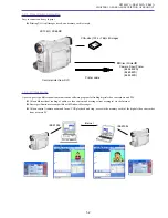
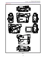
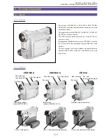
Page 12: ...ZR70 MC A ZR65 MC A ZR60 A CHAPTER 1 GENERAL DESCRIPTION OF PRODUCT 1 9 External View Fig 1 1 ...

Page 13: ...ated keys are used ZR70 MC A and the feel of the colored clear keys enhanced both ZR65 MC A and ZR60 A The front terminal cover is now finished with metallic paint on all models ZR70 MC A ZR65 MC A and ZR60 A for a more deluxe look 2 1 2 Variation Champagne metallic same as ZR50 MC A Illuminated keys with white LEDs EVF Silver paint ZR70 MC A ZR65 MC A ZR 60 A Blue clear keys EVF Silver paint 20x ...

Page 14: ... of units manufactured has been increasing substantially The DMC III digital mechanism chassis was developed with the aims of further improving reliability by drastically reducing the number of component parts and also enhancing quality At the same times the developers worked to reduce the cassette loading time and improve ease of operation 2 2 2 Configuration Comparison of DMC II and DMC III Digi...

Page 15: ...ZR70 MC A ZR65 MC A ZR60 A CHAPTER 1 GENERAL DESCRIPTION OF PRODUCT 1 12 2 2 3 DMC III Slide In Out Status 23 7mm 39 4mm 56mm 73mm Slide in status Slide out status ...

Page 16: ...g switch The camcorder switches to the Direct Print mode Turn the Multi switch to select Print Cancel No of Copies or Style Border or No Border and specify the setting for the desired item Refer to page 60 for details of the screen The direct print setting specifications are basically the same as those for a digital camera However the card image advance item on the setting screen is unique to vide...

Page 17: ...sing LCD ZR65 MC A BP 508 Approx 100 minutes 55 minutes using CVF Approx 75 minutes 40 minutes using LCD BP 512 Approx 180 minutes 95 minutes using CVF Approx 140 minutes 75 minutes using LCD BP 522 Approx 370 minutes 195 minutes using CVF Approx 295 minutes 155 minutes using LCD BP 535 Approx 590 minutes 315 minutes using CVF Approx 470 minutes 250 minutes using LCD ZR60 A BP 508 Approx 100 minut...

Page 18: ...s filter Can use WD 30 5 TL 30 6 FS 30 5U or WA 30 5 WA 30 5 is supplied with ZR70 MC A model only 5 2 12 Lens hood None 5 2 13 Lens cap Included Screw on type 5 3 Digital zoom tape recording only ZR70 MC A To 88x approx 246 4 mm 35 mm equivalent 4 752 mm to 440x approx 1 232 mm 35 mm equivalent 23 760 mm ZR65 MC A To 80x approx 224 mm 35 mm equivalent 4 320 mm to 400x approx 1 120 mm 35 mm equiva...

Page 19: ...1 250 second in Card mode ZR70 MC A ZR65 MC A models When image stabilizer is ON 1 100 second flickering sensed 1 120 second flickering not sensed When image stabilizer is OFF 1 100 second flickering sensed Low speed shutter 1 15 second Low Light mode Low Light mode constant speed 1 60 second to 1 8 second Night mode Super Night mode 1 8 second to 1 500 second automatic setting in Night mode and S...

Page 20: ... sustained until this function is turned off Multi screen A number of images equal to the number of screen windows are captured and displayed manually or each time a fixed number of seconds passes The display remains until this function is turned off Card mix A mixture of included sample images images recorded to a card and camera motion video is displayed ZR70 MC A ZR65 MC A model only 5 11 1 Fad...

Page 21: ...e 5 13 7 Remote control reception ON OFF Possible This can be done in Camera mode and VCR mode through menu selection 5 13 8 Headphone volume adjustment Possible Can be adjusted using the multi switch 6 Recorder 6 1 Recording functions Camera shooting and recording DV input recording analog input recording 6 1 1 Recording format Consumer electronics digital DVC SD specs 6 1 2 Tape speed SD spec Ap...

Page 22: ...log value Approx 430 TV lines screen center b Audio signals Signal type Stereo audio signals Output impedance 3 KΩ or less Output signal level 10dBv with 47 KΩ load Frequency characteristic 80 Hz to 12 KHz 1 KHz reference 10 dB range Audio signal S N For microphone input 48dB or higher For external microphone input 48dB or higher 6 7 3 S video terminal Signal configuration NTSC Y C separated video...

Page 23: ...r yyyy for file number and z for letter from A to Z Corresponds to motion video file with same file number DCF folder and file namd DCIM xxxCANON AUT_yyyy JPG xxx Folder No yyyy File No File number Files are managed internally in the format Folder Number File Number Photographed images are assigned file numbers between 0001 and 9900 and 100 image files are stored per folder Individual folders are ...

Page 24: ...es as a landmark The common portions in each image should constitute between 30 and 50 of the frame width Also unevenness at the top and bottom should not exceed 10 of the frame height 6 9 Digital feature playback functions The following modes are provided Fader Effect Multi screen Can be executed once when Fader mode is displayed in conjunction with pressing the button the mode display disappears...

Page 25: ...29 hours minutes seconds frames 6 11 5 Photo search This function searches for images shot in Photo mode Forward reverse photo search use the keys on the remote control after selecting Photo Search with the remote control Search Select key Values can be entered in a range of up to the 10th photo from the current position 6 11 6 Date search If there is more than one recording date this function cue...

Page 26: ... 5mm 4 pole pin jack yellow input and output also serves as headphone terminal 7 4 External microphone input terminal φ 3 5mm stereo mini jack 7 5 Headphone terminal φ 3 5mm stereo mini jack also serves as AV terminal 7 6 Memory card connection terminal Special multi pin ZR70 MC A ZR65 MC A only 7 7 Battery terminal Special 3 pin 7 8 DC IN terminal φ 3 4mm jack 7 9 USB port 5 pin mini B Receptacle...

Page 27: ...s Controller MiniDV Video Cassette CG 570 Battery Charger CA 570 Compact Power Adapter TV VCR SC 1000 Soft Carrying Case S 150 S video Cable Digital Device BP 500 Series Battery Pack CB 570 Car Battery Cable Computer SC A50 Soft Carrying Case Commercially available DV Cable BP 500 Series Battery Pack STV 250N StereoVideo Cable WD 30 5Wide converter WA 30 5Wide Attachment FS 30 5U Filter Set TL 30 ...

Page 28: ...60 Zooming stopped W T Zoominging to tele end W T Zoominging to wide end W T Image stabilizer display The image stabilizer is ON The image stabilizer is OFF No display Recording mode display SD mode During SP recording During LP recording Operation mode display During mirror shooting mirror mode LCD Recording Red display Record pause Green display Playback is stopped Green display Cassette is ejec...

Page 29: ... mode is selected Spotlight mode is selected Surf snow mode is selected Low light mode is selected Night mode is selected Super Night mode is selected ZR70 MC A only Program AE mode menu Super Night mode is for ZR70 MC A only Tape counter display Time code display Not entered Zero Set Memory M M M Not entered M AE shift display Minimum exposure value When standard value is set Maximum exposure val...

Page 30: ...At end of tape Not entered Tape warning display Flashes red Other No display Focus mode display AF OFF Infinity focus AF ON No display Self timer display Self timer standby Timer operating Other No display Battery power display Approx 75 remaining Approx 50 remaining Approx 25 remaining Approx 0 remaining Flashes red Power adapter is connected No display ...

Page 31: ...y 1 60 sec 1 100 sec 1 250 sec 1 500 sec 1 1000 sec 1 2000 sec Auto No display White balance display Set Indoor preset Outdoor preset Auto No display Condensation warning display Remote sensor code display Code 1 setting Code 2 setting Sensor OFF Headphone volume adjustment display Volume OFF Card mix display For ZR70 MC A ZR65 MC A only ...

Page 32: ...1 29 MENU INDICATION NORTH AMERICA MODEL REMARKS Digital feature display Fade Tigger Wipe horizontal Corner Wipe Jump Flip Puzzle Zigzag Beam Tide Art Black and White Sepia Mosaic Ball Cube Wave Color Mask Mirror Multi screen Feature OFF No display Digital feature menu ...

Page 33: ...lection In Multi Screen Speed Selection In Multi Screen Count Selection Digital Feature selection Press the D E SEL button in Camera mode VCR mode or Card Recording mode The line where the cursor is located in the menu is surrounded with a turquoise frame The previously selected items and the corresponding settings are shown in yellow ...

Page 34: ...d screen display Wind screen ON ON Wind screen OFF No display Time and date display When time and date are not set Audio mode display 16 bit is selected 12 bit is selected 16 9 mode display 16 9 mode is selected Other No display Half press lock display Photo mode display Normal recording No display Photo mode is selected ...

Page 35: ... is selected 12 bit Mix variable is selected 16 bit No display Audio Mix Balance display ST 1 ST 2 1 0 ST 1 ST 2 1 1 ST 1 ST 2 0 1 Recording mode display During SP recording During LP recording Operating mode display During Recording Red display During Recording pause Cassette is ejected Playback is stopped Playback Fast forward Rewind No tape Fast forward playback 2 SP playback 1 SP playback Slow...

Page 36: ...ate photo search Reverse date photo search FF return REW return AV insert pause AV insert recording Audio dubbing pause Audio dubbing recording Red display Tape counter Time code display Not entered Zero set memory Same as during Camera mode Remaining tape display Same as during Camera mode Audio dubbing insert or search operation display AV insert is selected Audio dubbing is selected Date search...

Page 37: ...Speaker volume adjustment display Volume OFF Headphone volume adjustment display Same as during Camera mode Data code display Data code setting Date and time Camera data Dateandtime cameradata Date time setting Time setting Date setting Date and time selection Camera data F number display F number closed This product has no F number full close When not entered function Shutter speed display The sh...

Page 38: ...and time setting are selected Not entered Date display Not entered Wind screen display Same as during Camera mode Audio data display Audio dubbing audio input terminal Audio dubbing micro phone input terminal Audio mode display Same as during Camera mode 16 9 mode display Same as during Camera mode DV display During DV input AV input DV signal conversion Other No display ...

Page 39: ...ON NORTH AMERICA MODEL REMARKS Card Camera mode Zoom display Same as during Camera mode Card recording image quality display Program AE mode display Full Auto mode Auto mode Sports mode Portrait mode Spotlight mode Surf snow mode Low light mode Low light mode ZR70 MC A only Stitch assist number of photos display Card access display ...

Page 40: ...a mode Card motion video recording time display 320 240 pixels 160 120 pixels Still image size display 1024 768 pixels 640 480 pixels Motion video size display ZR70 MC A only 160 120 pixels Focus mode display Same as during Camera mode Self timer display Same as during Camera mode Battery power display Same as during Camera mode Shutter speed display Lithium battery low power warning display Same ...

Page 41: ... OF PRODUCT 1 38 MENU INDICATION NORTH AMERICA MODEL REMARKS Digital feature display Same as during Camera mode but with no fader function Time and date display Same as during Camera mode Date and time only Half press lock display Same as during Camera mode ...

Page 42: ... MC A only MENU INDICATION NORTH AMERICA MODEL REMARKS Card play mode Slideshow display DPOP designation display Protect mark display DCF file name display Directory Number File Number Card access display Writting to card Shown in red displayed in sequence Reading from card Shown in green displayed in sequence ...

Page 43: ...ng number of images recorded on card 0 recorded images 9th of 99 recorded images 99th of 99 recorded images 9999th of 9999 recorded images Image size display Volume display ZR70 MC A only Same as during VCR mode During moving image playback Data code display Same as during VCR mode Date and time only Slideshow operation guidance display During slideshow execution ...

Page 44: ...1 500 1 1000 1 2000 D ZOOM OFF 88 80 72 Lithium battery 88 80 72 440 400 360 IMAGE S ON ON Lithium battery OFF 16 9 ON OFF Lithium battery OFF WHIT BAL AUTO AUTO Lithium battery SET INDOOR OUTDOOR RETURN VCR SET UP REC MODE SP SP Lithium battery LP AV PHONES AV AV Lithium battery PHONES RETURN AUD SET UP WIND SCREEN ON ON Lithium battery OFF AUDIO MODE 16 bit 12 bit Lithium battery 12 bit RETURN D...

Page 45: ...LOR 3 GREEN TURQUOISE Lithium battery ORANGE BLUE YELLOW TURQUOISE PURPLE WL REMOTE 4 Lithium battery OFF BEEP 2 ON ON Lithium battery OFF T ZONE DST 4 LONDON N Y Lithium battery LONDON PARIS PARIS CAIRO MOSCOW DUBAI KARACHI DACCA BANGKOK H KONG TOKYO SYDNEY SOLOMON WELLGTN SAMOA HONOLU ANCHOR L A DENVER CHICAGO N Y CARACAS RIO FERNEN AZORES AZORES D TIME SEL 4 JAN 1 2003 JAN 1 2003 Lithium batter...

Page 46: ...t power on and when the menu is closed Note that this applies to the D TIME SEL only when OFF is selected for D T DISPLAY Also WL REMOTE OFF is displayed at all times MAIN MENU ITEM SUB MENU ITEM SETTINGS DEFAULT BACKUP MY CAMERA SHTR SOUND PATTERN1 PATTERN1 Lithium battery PATTERN2 PATTERN3 S UP SOUND PATTERN1 PATTERN1 Lithium battery PATTERN2 PATTERN3 S STOP SOUND PATTERN1 PATTERN1 Lithium batte...

Page 47: ...is STEREO 2 turned off MIX FIXED MIX VARI MIX BALANCE Lithium battery AUDIO DUB AUDIO IN AUDIO IN Lithium battery MIC IN WIND SCREEN ON ON Lithium battery OFF RETURN CARD SET UP 2 SI QUALITY SUPER FINE FINE Lithium battery FINE NORMAL MOVIE SIZE 320 240 320 240 Lithium battery 160 120 IMAGE NOS RESET CONTINUOUS Lithium battery CONTINUOUS RETURN CARD OPER 2 COPY Go to Copy execution screen RETURN D...

Page 48: ...battery ORANGE BLUE YELLOW TURQUOISE PURPLE WL REMOTE 2 Lithium battery OFF BEEP 1 ON ON Lithium battery OFF T ZONE DST 5 LONDON N Y Lithium battery LONDON PARIS PARIS CAIRO MOSCOW DUBAI KARACHI DACCA BANGKOK H KONG TOKYO SYDNEY SOLOMON WELLGTN SAMOA HONOLU ANCHOR L A DENVER CHICAGO N Y CARACAS RIO FERNEN AZORES AZORES D TIME SEL 5 JAN 1 2003 JAN 1 2003 Lithium battery 12 00 AM 12 00 AM DEC 31 203...

Page 49: ...n screens other than the menu screen displayed for 4 seconds at power on and when the menu is closed Note that this applies to the D TIME SEL only when OFF is selected for D T DISPLAY MAIN MENU ITEM SUB MENU ITEM SETTINGS DEFAULT BACKUP MY CAMERA SHTR SOUND PATTERN1 PATTERN1 Lithium battery PATTERN2 PATTERN3 S UP SOUND PATTERN1 PATTERN1 Lithium battery PATTERN2 PATTERN3 S STOP SOUND PATTERN1 PATTE...

Page 50: ...SIZE 320 240 320 240 Lithium battery 160 120 FILE NOS 1 RESET CONTINUOS Lithium battery CONTINUOS RETURN VCR SET UP AV PHONES AV AV Lithium battery PHONES RETURN AUD SET UP WIND SCREEN ON ON Lithium battery OFF RETURN DISP SET UP BRIGHTNESS 2 Lithium battery LCD MIRROR 2 ON ON Lithium battery OFF TV SCREEN ON ON Lithium battery OFF D T DISPLAY 2 ON OFF Lithium battery OFF DEMO MODE ON OFF Lithium ...

Page 51: ...ly MAIN MENU ITEM SUB MENU ITEM SETTINGS DEFAULT BACKUP SYSTEM T ZONE DST 2 LONDON N Y Lithium battery LONDON PARIS PARIS CAIRO MOSCOW DUBAI KARACHI DACCA BANGKOK H KONG TOKYO SYDNEY SOLOMON WELLGTN SAMOA HONOLU ANCHOR L A DENVER CHICAGO N Y CARACAS RIO FERNEN AZORES AZORES D TIME SEL 2 JAN 1 2003 JAN 1 2003 Lithium battery 12 00 AM 12 00 AM DEC 31 2030 11 59 PM RETURN MY CAMERA SHTR SOUND PATTERN...

Page 52: ...rmat screen RETURN CARD OPER PROTECT Go to Image Protect screen Index screen PRINT ORDER Go to Print order screen RETURN VCR SET UP REC MODE SP SP Lithium battery LP AV PHONES AV AV Reset when power is PHONES turned off RETURN DISP SET UP BRIGHTNESS 1 Lithium battery DISPLAY ON ON Lithium battery OFF D TIME SEL 2 DATE DATE TIME Lithium battery TIME DATE TIME RETURN SYSTEM BUTTON LIGHT 3 ON ON Lith...

Page 53: ...ST 4 LONDON N Y Lithium battery LONDON PARIS PARIS CAIRO MOSCOW DUBAI KARACHI DACCA BANGKOK H KONG TOKYO SYDNEY SOLOMON WELLGTN SAMOA HONOLU ANCHOR L A DENVER CHICAGO N Y CARACAS RIO FERNEN AZORES AZORES D TIME SEL 4 JAN 1 2003 JAN 1 2003 Lithium battery 12 00 AM 12 00 AM DEC 31 2030 11 59 PM RETURN PRINT ORDER 5 Go to the Print order screen ...

Page 54: ...en connected to a camera direct printer Note that this applies to the D TIME SEL only when OFF is selected for D T DISPLAY MAIN MENU ITEM SUB MENU ITEM SETTINGS DEFAULT BACKUP MY CAMERA CREATE START UP Go to the Startup screen creation screen SEL S UP IMG NO PICTURE CANON LOGO Lithium battery CANON LOGO MY PICTURE SHTR SOUND PATTERN1 PATTERN1 Lithium battery PATTERN2 PATTERN3 S UP SOUND PATTERN1 P...

Page 55: ... ZR65 MC A ZR60 A CHAPTER 1 GENERAL DESCRIPTION OF PRODUCT 1 52 MENU INDICATION NORTH AMERICA MODEL REMARKS Slideshow screen Index screen Image protect screen Print order screen 5 6 Card Related Screen Displays ...

Page 56: ... A ZR65 MC A ZR60 A CHAPTER 1 GENERAL DESCRIPTION OF PRODUCT 1 53 MENU INDICATION NORTH AMERICA MODEL REMARKS Copy screen Copy selection screen Copy execution screen Copy selection screen Copy execution screen ...

Page 57: ... MC A ZR60 A CHAPTER 1 GENERAL DESCRIPTION OF PRODUCT 1 54 MENU INDICATION NORTH AMERICA MODEL REMARKS Image erase screen Image erase selection screen Erasing one image Warning Erasing in progress Erasing all images ...

Page 58: ...ZR70 MC A ZR65 MC A ZR60 A CHAPTER 1 GENERAL DESCRIPTION OF PRODUCT 1 55 MENU INDICATION NORTH AMERICA MODEL REMARKS Format screen Format execution confirmation screen Format execution screen ...

Page 59: ...ZR65 MC A ZR60 A CHAPTER 1 GENERAL DESCRIPTION OF PRODUCT 1 56 MENU INDICATION NORTH AMERICA MODEL REMARKS Card mix selection screen Mix type setting screen Animation type setting screen Mix level setting screen ...

Page 60: ...A ZR60 A CHAPTER 1 GENERAL DESCRIPTION OF PRODUCT 1 57 MENU INDICATION NORTH AMERICA MODEL REMARKS Stitch assist screen My camera settings My camera settings screen Startup image creation screen Select recording position ...

Page 61: ...L DESCRIPTION OF PRODUCT 1 58 MENU INDICATION NORTH AMERICA MODEL REMARKS My camera settings Record execution confirmation Message during image creation Startup image selection screen Shutter sound selection screen Startup sound selection screen ...

Page 62: ...PTER 1 GENERAL DESCRIPTION OF PRODUCT 1 59 MENU INDICATION NORTH AMERICA MODEL REMARKS My camera settings Start stop selection screen Self timer sound selection screen PC connection screen displays USB connection IEEE1394 connection ...

Page 63: ...creen L Size Borderless Style Copies 1 Print Cancel Now printing 1 1 SET L Size Borderless Print stop screen L Size Borderless OK Cancel Two sheets remain Cancel Two sheets remain Cancel SET L Size Borderless OK Cancel Cancel Now printing 1 3 L Size Borderless SET SET L Size Borderless Style Copies 1 OK Cancel SET Direct Print Cancel Cancel selection screen 5 7 Direct Print Setting Screen ...

Page 64: ...ERICA MODEL Direct print setting screen Number of copies setting screen L Size Bordered Style Copies Print Cancel SW 1 L Size Bordered Style Copies Print Cancel SET L Size Bordered Style Copies Print Cancel 2 L Size Bordered Style Copies Print Cancel Quantity set by Multi switch Setting 1 Setting 2 ...

Page 65: ...T SELECT SET Style Paper Setting L Size Paper Setting L Size SET MENU SELECT Go to the style setting screen using MENU buttons MENU MENU L Size Borderless Style Copies Print Cancel 1 L Size Borderless Style Copies Print Cancel 1 Style Paper Setting LL Size MENU Style Borders Borderless MENU Style Borders Borderless MENU Style Borders Bordered MENU Style SELECT ...

Page 66: ...op screen L Size 9999 Borderless OK Cancel Set print Mode cancel Now Printing 1 9999 Cancel SET SET L Size 9999 Borderless Cancel Print restart screen L Size 9999 Borderless Style OK Resume Cancel Now Printing 1 9999 Print remaining Images SET L Size 9999 Borderless Cancel Style setting screen L Size 9999 Borderless Style OK Resume Cancel Style is changed SET L Size 9999 Borderless OK Resume Cance...

Page 67: ...d if a cassette is inserted a REMOVE THE CASSETTE message appears THE TAPE IS SET FOR ERASURE PREVENTION When REC is pressed in a mode that allows transition to REC in VCR mode if the cassette is set for erasure prevention In Camera mode when the power is turned ON when the Start Stop button is pressed and when a cassette is inserted if the cassette is set for erasure prevention TAPE END When the ...

Page 68: ...ARD When there is no card in the camcorder socket for ZR70 MC A ZR65 MC A model NO IMAGES When there are no images to be played in the card for ZR70 MC A ZR65 MC A model THE CARD IS SET FOR ERASURE PREVENTION When an attempt is made to record on an SD card set for erasure prevention in a mode that allows card recording VCR mode Card Recording mode for ZR70 MC A ZR65 MC A model NOW CREATING START U...

Page 69: ... Supply Lithium Coin Primary Battery The table below lists the item excluding menu items backed up by the main power supply or backup power supply lithium coin primary battery Item Default Remarks Digital zoom position Optical tele end WB data SET Time and date settings auto date 2003 1 1 12 00 AM Menu cursor position Very top Time code Mix balance ZR70 MC A ZR65 MC A only Center Headphone volume ...

Page 70: ...FF On screen ON OFF Backup Zero Set Memory counter value CAM Backup Camera Card Camera ZR70 MC A ZR65 MC A menu item settings Digital Effects selection Backup Independent Fader CAM Backup Independent Effects Backup Independent Multi screen speed Backup Independent Multi screen number of screens Backup Independent Mix key selection in Card Mix Backup CAM ZR70 MCA ZR65 MCA only Mix level in Card Mix...

Page 71: ...ontrol code setting Backup Recording mode setting Backup Data code setting Backup Time and date selection setting Backup LCD brightness adjustment Backup Text display during playback ON OFF Backup Date Auto display ON OFF Backup Bilingual setting Reset set to Main Sub Audio dubbing input setting Backup Wind screen ON OFF Backup LINE IN audio mode setting Backup AV headphone selection Reset set to ...

Page 72: ... timer ON OFF Backup Backup On screen ON OFF Backup Backup Zero Set Memory counter value CAM Backup Backup Camera Card mode ZR70 MC A ZR65 MC A menu item settings D Effects selection Backup Independent Backup Independent Fader CAM Backup Independent Backup Independent Effects Backup Independent Backup Independent Multi screen speed Backup Independent Backup Independent Multi screen number of scree...

Page 73: ...tween Program AE mode in tape recording and various shooting functions ZR70 MC A ZR65 MC A only Super Night mode is limited to the ZR70 MC A 7 2 On Screen Turn ON OFF of the On screen function is performed through the infrared remote controller or from the menu The default setting is ON in Camera mode and OFF in VCR mode Program AE Mode Item Recording medium Autofocus ON OFF Forced ON Shutter spee...

Page 74: ...attery indicator is not displayed However the low power warning is displayed if the voltage drops below the low power warning level due to an abnormality When the voltage is restored above the low power warning level the low power warning disappears The low power warning is displayed when the battery terminal voltage falls to approx 6 3 V or less for this product 7 5 System Data Displays The time ...

Page 75: ...EEP BEEP BEEP When EJECT cover is opened all the way even when power is OFF PIP PIP When recording is started Camera mode PIP When recording is paused Camera mode PIP PIP When Photo button is half pressed PIP PIP When photo recording starts PIP When a condensation or a mechanical error occurs or five seconds BEEP 5 times before the REC PAUSE five minute timer ends When the SET button is pressed on...

Page 76: ...o input at this time 4 To start recording press on the remote control This starts recording of video audio etc through the terminal selected in step 2 Press to toggle between recording and pausing 5 Press to stop recording Recording is stopped If DV input disappears during DV recording then recording is stopped If a recording source is input to the DV terminal during analog line recording recordin...

Page 77: ...ing playback of a tape recorded in Camera 16 9 mode or a tape containing system data related to the aspect ratio NTSC 16 9 Full mode 4 3 Letter Box mode identification signal output PAL 16 9 Full mode identification signal output 2 Video ID1 output When a Full mode squeezed video signal consisting of 16 9 video compressed to 4 3 is output from the composite video terminal or S terminal a video ID ...

Page 78: ... When built in microphone input is used The S terminal and AV terminal are set to Output The speaker is off and line motion is possible 7 12 3 Audio Dubbing Procedure 1 In VCR mode play and pause the tape at the position where you want to add audio dubbing Next press the Audio dubbing button on the remote control The camcorder switches to Audio Dubbing mode Audio Dubbing pause and Audio Dubbing pa...

Page 79: ...V terminal are OFF The speaker output is muted 7 13 3 AV Insert Procedure 1 In VCR mode play and pause the tape at the position where you want to insert AV Next press the AV Insert button on the remote control The camcorder switches to AV Insert mode AV Insert pause and AV Insert pause is displayed on the LCD panel CVF 2 Push the Pause button and input the video and audio This starts the AV insert...

Page 80: ... protection CGMS 00 If a value other than 00 is detected for CGMS then the A D signal conversion function is closed the LCD panel CVF changes to blue background the audio output is muted and the following warning message is displayed COPYRIGHT PROTECTED DUBBING RESTRICTED 7 15 Multi Switch VCR operations and various settings can be performed in this mode When the Switch is Turned When Setting Swit...

Page 81: ...utline of Signal Processing Circuit 2 10 4 2 Camera Card Signal Processing 2 11 4 2 1 Camera Motion Picture Recording 2 11 4 2 2 Card Still Picture Recording 2 11 4 2 3 Card Motion Picture Recording 2 12 4 3 Recorder Signal Processing 2 13 4 4 Audio Signal Flow 2 14 5 System Control Servo 2 15 5 1 Outline of System Control Servo 2 15 5 2 Major Functions of Each Microcomputer 2 16 5 3 Servo Control...

Page 82: ...301 VIC3 Digital VCR signal processing LSI IEEE1394 interface FR MI COM and USB interface IC2302 SDRAM Memory for VIC3 64M MO Driver Section IC300 OPE AMP Operational amplifier for reel sensor IC301 MOTOR DRIVE Drum capstan and loading motor driver Audio Section IC801 AUDIO INTERFACE Analog input output signal processing IC802 SP DRIVER Speaker amplifier IC803 4V REGULATOR 4V regulator for speaker...

Page 83: ...B Signal transfer from CAC P C B to CVF LCD back light LED turn on 6 JACK P C B AV MIC S JACK USB interface Remoto control signal receiver sensor white LED IC1601 P SENSOR GYRO Pitch direction angular speed detection IC1602 Y SENSOR GYRO Yaw direction angular speed detection ...

Page 84: ...cted with power source not supplied with power is inserted into the main unit power is not turned on even if the battery is mounted A changeover of main power to the battery is not made since an event of DC jack mechanism detection takes precedence 2 1 Startup of Power Supply Fig 2 1 3 13 5 7 4 76 77 66 67 14 4 12 11 97 18 14 62 10 52 73 41 71 25 2 DET RESET SW E3V E3 DET VCC CN4001 LITHIUM BATTER...

Page 85: ...main power thus supplied is converted to 3V power which is output as E3V from pin 14 of IC102 Furthermore through the internal switch the main power is converted to LI3V which is output from pin 12 of IC102 as a power voltage for driving the MODE MI COM Supplied with the main power IC102 outputs the L signal from its pin 4 When the MODE MI COM receives the L signal and the two signals output from ...

Page 86: ... 2 5V 1 4V power source DVDD 1 4V MACS 1 4V AVDD 1 4V LCD drive power source 8V 8 5V 15V CCD drive power source 7V 15V 2 P5 VTR UNREG FU3202 4 7V power source AA 4 7V VIF 4 7V HA 4 7V 5V power source POW 5V LCD 5V VCR UNREG 3 MECHA UNREG FU3203 DRUM CAPSTAN 4 DC DC UNREG FU3204 DC DC CONVERTER 5 SHOE UNREG FU3205 Accessory shoe power source 6 MI COM UNREG FU1801 MI COM UNREG BATTERY Fig 2 2 2 DC 5...

Page 87: ...D 10V LCD 8 5V REG REG 62 11 PWM 28 30 56 40 PWM LCD 15V VTR ON SDRAM 2 7V DIF 2 7V AVDD 2 7V A 3V HA 3V Q3205 MAIN P C B 31 60 21 Q3207 REG LPF P 5V HA 4 7V LPF LPF LPF LPF LCD 5V LPF VIF 4 7V LPF REG REG LPF LPF LPF LPF LPF LPF LPF LPF LPF LPF LPF LPF LPF MACS 1 4V LPF REG PWM CH 5 UNREG DRUM VM AA 4 7V 57 37 Q3206 REG PWM CH 4 UNREG CCD 15V CCD 7V 64 5 REG PWM CH 8 UNREG DVDD 1 4V AVDD 1 4V DVD...

Page 88: ...mination and DC jack input detection 2 IC 1802 OPE AMP Signal amplification for detecting charging current 3 Q1802 Q1803 MOS form FET Power supply changeover switch 4 Q1804 Q1805 TRANSISTOR Trickle charge switch Fig 2 4 CHAGE INIT CHG1 INIT CHG2 A D I A D V DC JACK DET DC JACK DET UNREG DET BATT AD BATT INFO AD Q1803 Q1805 Q1804 Q1802 IC1802 CN3202 5 6 3 4 2 1 BATT BATT BATT INFO AD BATT E3 BATT E...

Page 89: ...0 to start charging Conditions Detection Source of detection Main unit power is turned OFF MODE MI COM pin 76 77 POWER SW Battery is installed MODE MI COM pin 88 Battery D terminal BATT INFO AD CN3202 pin 2 DC JACK is inserted MODE MI COM pin 71 DC JACK DC JACK DET CN3201 pin 3 DC JACK input voltage is 8 4 0 3V MODE MI COM pin 87 BATT AD DC JACK MODE MI COM pin 73 CN3201 pin 2 UNREG DET ...

Page 90: ...icated and charging is turned OFF if the charging voltage is 1 8A or higher detected voltage 2 7V Charging is turned OFF if the charging current is 70mA or lower If the battery is not installed removed after completion of charge charging does not start unless the battery voltage becomes 7V or lower Charging is allowed to start provided that the UNREG voltage is 8 4 0 3V before starting the chargin...

Page 91: ...ssing circuit and the flow of video and audio signals Fig 2 6 LENS CCD P C B CARD P C B JACK P C B MAIN P C B LCD P C B CAC P C B MEMORY CARD IC1102 MACS IC2100 VIF2 IC801 AIF3 IC802 SP DRIVE LCD CVF LCD IC1001 CCD IC2303 SDRAM IC903 EVF DRIVE IC2000 VRP2 IC1101 SDRAM IC2301 VIC3 IC501 EVF DRIVE IC1002 TG CDS AGC AD USB DIF FR MICOM MIN AV JACK DV TERMINAL USB TERMINAL MIC SPEAKER REC PB HEAD ...

Page 92: ... signal processing GRAB CDS AGC AD TG IC1002 CARD IF proc resize nr VIC3 IC2301 FR MI COM CCD IC1001 IC1102 36MHz 10bit 18MHz SDRAM IF AIF IC801 32 bit 64 Mbit SDRAM IC1101 Fig 2 8 JPEG Audio SDRAM IF CARD IF proc resize nr VIC3 IC2301 SD CARD DMA FR MI COM RAW YCC 1 YCC 2 AIF IC801 USB CDS AGC AD TG IC1002 36MHz 10bit 18MHz CCD IC1001 IC1102 Camera signal processing GRAB 64 Mbit SDRAM IC1101 Synt...

Page 93: ...t processing operation are carried out This circuit carries out various camera signal processing operations EIS AWB etc and digital effect processing It also performs multimedia application signal processing mainly for still image recording Feature engine High speed card interface JPEG Audio data compression ADPCM USB 1 1 function SDRAM IC1101 Field memory for camera signal processing and digital ...

Page 94: ...input the data enters VIC3 signal processing circuit via the opposite route VRP2 IC2000 Recording data of 41 85 Mbps output from VIC3 is amplified at VRP2 and is recorded on magnetic tape while undergoing head switching of CH 1 CH 2 with a switching pulse At playback the head output signal is amplified and sent to VIC3 VIF2 IC2100 Y and C signals sent from VIC3 are output as Y C signals for S term...

Page 95: ...nal from the FR MI COM is generated in the circuit and changed over in the AIF The microphone amplifier HPF ALC A D D A and digital I F circuits are contained in this IC It is also used for changeover between ordinary voice sound and beep sound SPEAKER DRIVER IC802 This integrated circuit is used for speaker drive operation Fig 2 11 IC802 SPEAKER DRIVER FR MI COM IC801 AIF3 IC1102 MACS IC2301 VIC3...

Page 96: ...CAC P C B HEAD REMOTE CONTROL SIGNAL RECEIVER M FG PG DRUM CAPSTAN LOADING FG M M IC1202 IRIS DRIVE IC901 EEPROM IC902 SERI PARA CONVERTER ZOOM SW START STOP SW PHOTO SW DIAL SW R KEY EJECT SW POWER SW IC903 LCD DRIVER IC1501 EVF DRIVER IC101 EEPROM IC1701 MOTOR DRIVER IC3201 DC DC CONVERTER FR MI COM IC1102 MACS VIC IC100 MODE MI COM IC2100 VIF2 IC801 AIF3 IC2000 VRP2 IC2300 FLASH MEMORY CARD IC1...

Page 97: ... control CCD drive control AE AF AWB control EIS Electric Image Stabilizer control OSD On Screen Display bitmap control The FR microcomputer in this machine does not have a dedicated EEPROM Since a flash ROM is used for the FR microcomputer as a substitute for the EEPROM it is required to update the flash ROM after adjustment and data modification regarding the FR microcomputer 2 MODE MI COM IC100...

Page 98: ...e FG PG and PB RF signals from the motor and sends the detected signal information to the FR MI COM Then the FR MI COM generates an error signal to be output to the VIC Thereafter the VIC outputs an error signal PWM which is driven on the MAIN P C B for sending a control voltage to the motor driver IC Fig 2 13 VIC3 S REEL Hall SENSOR LOADING MOTOR DRUM MOTOR CAPSTAN MOTOR T REEL Hall SENSOR LOAD O...

Page 99: ...nection mode the USB terminal and the memory card are connected through the USB controller The FR MI COM performs control of changeover between the card camera mode and the personal computer connection mode Fig 2 14 Card camera mode of signal flow Personal computer connection mode of signal flow IC1001 CCD IC1002 TG CDS AGC AD IC1102 MACS IC2301 VIC3 MEMORY CARD USB TERMINAL Still Picture Signal P...

Page 100: ... Error stop Error stop Error stop Reel error Error stop Error stop Error stop Error stop Loading error Pop up Pop up Error stop Error stop Error stop Kind Condition Detection Drum error Error detecting mode Starting steady D FG FG frequency when steady 900Hz Error detecting level Starting Beyond 80 150 Steady 30 max Error detecting time Starting 5sec Steady 0 5sec Capstan error Error detecting mod...

Page 101: ... 4 2 1 Mechanical Error Normal Mode 3 8 4 2 2 Mechanical Error Analysis Mode 3 9 4 3 Cleaning Mode 3 10 4 4 Commands Particular to Camera 3 10 4 5 Checking the Lens Resetting 3 11 4 6 Functional Check of Control Keys and Switches 3 11 4 6 1 MODE MI COM Input Port 3 11 4 6 2 MODE MI COM A D Port 3 12 4 6 3 FR MI COM Input Port 3 12 4 6 4 FR MI COM A D Port 3 12 5 Service Hints 3 13 5 1 Arrangement ...

Page 102: ...e W L T 10mm 50m 0 16mm UL type double side coated adhesive tape Sheet Shield W H 250mm 250mm DY9 3036 000 General purpose shield material Item Name Item Number Purpose Remarks Alignment Tape Color bar master NTSC DY9 1380 000 Recorder electrical adjustment Alignment Tape tracking DY9 1379 000 Running adjustment DMC III Cassette Torque Gauge for DV DY9 1346 000 Running adjustment DMC III DV Cleani...

Page 103: ...r DY9 1387 000 to CN2900 3 Observe the PB RF waveform output from the extension con nector Tracking Adjustment 1 Remove the CASSETTE COVER referring to Fig 3 2 a 2 When the posts are going to be adjusted eject and remove the cassette once and perform the prospective adjustment as shown in Fig 3 2 b 3 Repeat the observation of the PB RF waveform and the prospective adjustment until fluctuation of e...

Page 104: ... Chapter 4 1 Disassembling and Reassembling Note 1 Referring to Fig 3 3 connect the required cables Note 2 Observe the signal in the same manner as that for setting A Note 3 For EJECT select the service mode and use the wireless remote controller Note Same manner for recorder keys Fig 3 3 MONITOR TV WIRELESS CONTROLLER CA 570 LEFT COVER UNIT JACK P C B CN2101 CN3201 REAR COVER UNIT CN101 ...

Page 105: ...or mechanical error detection DEW detection and low voltage detection are canceled 6 In the service mode the LCD mirror function is canceled 3 2 How to Change Over to Service Mode 1 Cassette for changeover to service mode DY9 1386 000 Set the CASSETTE SERVICE MODE in the equipment and load the data 2 Press the Dubbing key on the wireless remote controller that is set at Remote controller code 2 To...

Page 106: ...AUSE Remote Controller Code 2 setting No Key Designation in Normal Mode Key Designation in Service Mode Function 1 DUBBING SERVICEMODE Change over to service mode 2 SLOW NORMAL MODE Change over to normal mode 3 START STOP CS Increases CS by 1 4 SEARCH FUNCTION Increases FUNCTION by 1 5 SEARCH FUNCTION Decreases FUNCTION by 1 6 FRAME HIGH ADDRESS Increases HIGH ADDRESS by 1 7 FRAME HIGH ADDRESS Dec...

Page 107: ...ntly being read or set 00 FF 8 Indicates the mechanical status POPUP STBY LOAD1 LOAD2 STOP PLAY 9 Indicates the absolute track No 10 Indicates the mechanical error Main power supply backup 11 Indicates mechanical error history LITHIUM 3V battery backup 12 Indicates the version of the MAIN program in the FR MI COM 13 Indicates the version of the MODE MI COM 14 Indicates the version of the CAMERA pr...

Page 108: ...neous sync block of 64 track AUDIO sync blocks is indicated in two hexadecimal digits FF limitation is imposed on a value exceeding 255 Example 23 is indicated Number of erroneous sync blocks 35 Important After the adjustment set the DT to the product setting press STORE key at 1 of STEP 1 state Change to an AUDIO error rate In the product specifications the error rate on both chan nels in self re...

Page 109: ...ITHIUM 3V 3 The data backed up by the LITHIUM 3V can be reset by the STEP 1 operation shown below 4 For changeover to the mechanical error analysis mode perform the STEP 2 operation shown below 4 2 1 Mechanical Error Normal Mode Fig 3 10 Relevant errors are highlighted in purple E B D C S T L D TAPE END TAPE TOP DRUM ERROR CAPSTAN ERROR S REEL ERROR T REEL ERROR LOADING MTR ERROR DEW ERROR STEP PR...

Page 110: ...n sensitivity level CEh or 8Dh is listed in the Treel subfield of the Mecha Error field compare it with the data 3 If the data 3 is above the T reel error detection sensitivity level listed the error history should be T reel error 4 Unless S or T reel error is determined in step 2 or 3 above the error history should be the error condition specified in the Mechani cal Error Applicablity Table field...

Page 111: ...E DT WB SET 1 Make setting shown at right 2 08 3300 ST 2 Execute STORE Press PAUSE RD WB is set WB 1 Make setting shown at right 2 08 3301 ST LOCK 2 Execute STORE Press PAUSE RD WB is locked WB 1 Make setting shown at right 2 08 3302 ST TURBO 2 Execute STORE Press PAUSE RD WB high speed setting mode WB 1 Make setting shown at right 2 08 3303 ST OUTDOOR 2 Execute STORE Press PAUSE RD WB outdoor mod...

Page 112: ... 1 MODE MI COM Input Port STEP PROCEDURE Microcomputer operation CS Function ADDR MODE DT 1 1 Make setting shown at right 2 00 4663 RD RAM data indication MONITOR STEP NAME DESCRIPTION CS Function ADDR DATA BIT REMARK 1 V3ToM PC PC mode communication PC mode start 1 01 000A 4 25 Li3V Detect Detection of decrease in lithium 1 01 0007 3 battery voltage 64 PANEL Open SW LCD open detection 1 01 0002 6...

Page 113: ...P NAME DESCRIPTION CS Function ADDR DATA BIT REMARK 9 EXT DET External microphone detection 0 01 0000 7 Audio C 107 AV DET AV jack detect 0 01 0004 3 338 USB DET USB Detect 0 01 0009 5 268 REC PROOF Tape recording inhibited 0 01 000A 4 214 CARD PRO Card recording inhibited 0 01 000A 2 STEP NAME DESCRIPTION CS Function ADDR REMARK 339 SHOE ID1 AA SHOE ID1 0 02 000E 48 CASE IN Cassette detection 0 0...

Page 114: ...ERVICE HINTS 3 13 5 Service Hints 5 1 Arrangement of Circuit Boards The printed circuit boards are arranged as shown below Fig 3 12 JACK P C B OPERATION KEY EJECT P C B R KEY P C B D SW2 P C B CARD P C B LCD P C B DC P C B CVF P C B MAIN P C B CAC P C B CCD P C B ...

Page 115: ...2301 VIC3 IC2300 FLASH IC1102 MACS IC803 4V REGULATOR IC1101 SDRAM IC801 AUDIO INTERFACE IC802 SP DRIVER IC3202 2 7V REGULATOR IC3203 4 7V REGULATOR IC2302 SDRAM IC3201 DC DC CONVERTER CONTROL IC103 RESET IC100 MODE MI COM IC1802 OPE AMP IC3204 2 5V REGULATOR IC2100 VIF2 IC102 BACKUP IC300 OPE AMP MAIN P C B FU1801 FU3205 FU3201 FU3202 FU3204 FU3203 ...

Page 116: ... 15 Fig 3 14 CAC P C B JACK P C B LCD P C B IC1701 MOTOR DRIVE IC1002 TG CDS AGC AD IC1601 P SENSOR GYRO IC1502 EEPROM IC1501 EVF DRIVER IC1602 Y SENSOR GYRO IC901 EEPROM IC902 SERI PARA CONVERTER IC903 LCD DRIVE IC4201 DC DC CONVERTER CONTROL IC1202 IRIS DRIVE IC1001 V DRIVER ...

Page 117: ...llowing table shows the specified value of current consumption in each status Measurement condition Product status camera auto mode AF IS OFF LCD ON Approx 0 1A each smaller in case of CVF Preset voltage 7 4V POWER SW MODE Current consumption A CAMERA REC PAUSE 0 46 REC 0 51 VCR STOP 0 45 PLAY 0 54 POWER OFF 0 3 mA ...

Page 118: ...started to turn on various power supplies The FR MI COM is started to control the system Check Points 1 Key Inputs Check the key inputs at Power Switch in the SERVICE mode 2 Check of microcomputer to microcomputer communication If the microcomputer to microcomputer communication line is normal the version number of each microcomputer can be indi cated in the service mode Otherwise the communicatio...

Page 119: ... output If the blue back is confirmed the signal line subsequent to VIC3 is considered to be OK 3 Check of MACS generation signal white 100 or color bar P 3 10 The white 100 or color bar signals are generated by the MACS on the MAIN P C B In the service mode if the output of the white 100 or color bar signal is attained the signal line subsequent to MACS is considered to be OK 4 Check of CCD outpu...

Page 120: ... procedure 1 Observe a playback envelope If it is abnormal carry out tape path adjustment 2 Run a cleaning tape Use the cleaning tape of hard type DY9 1384 000 Playback time Hard cleaning tape DY9 1384 000 After replacement of the drum unit 25 seconds For cleaning 25 seconds per time Up to three times When using hard type cleaning tape select the cleaning mode on the product main unit Refer to 4 3...

Page 121: ...indow Setting The startup window user setting contains a default image at shipment from the factory If any other image is written over the default image it is deleted completely So be cautious in such cases as MAIN P C B replacement Default image Image file Contained in 7 Appendix User Setting ...

Page 122: ...MechaStopToEject0030 EJECT Tape inserted 8Dh 0AACD6 MechaStopToEject0040 EJECT Tape inserted 8Dh 0AAE32 MechaStopToEject0050 EJECT Tape inserted 0AAF06 MechaStopToEject0060 EJECT Tape inserted 0AAF98 MechaStopToEjectNoCas0010 EJECT Tape not inserted 0AB05A MechaStopToEjectNoCas0020 EJECT Tape not inserted 0AB11C MechaStopToEjectNoCas0030 EJECT Tape not inserted 0AB1D4 MechaStopToEjectNoCas0040 EJE...

Page 123: ...P FF 0AF62A MechaRewLoop REW 8Dh 0AF6D8 MechaRewSlowToRew Changeover REW 9 5 30 8Dh 0AF7AA MechaRewToRewSlow Changeover REW 30 9 5 8Dh 0AF856 MechaHSRevToRewSlow Changeover REV REW 9 5 8Dh 0AF902 MechaStopToRewSlow Changeover STOP REW 0AFC12 MechaRecLoop Rec 8Dh 0AFC8E MechaRecPauseToRec Rec start 0B000A MechaRecPauseToRec0010 Changeover to Rec start 0B0090 MechaRecPauseToRec0012 Changeover to Rec...

Page 124: ...haHSCueLoop CUE 8Dh 0B3664 MechaFFToHSCue Changeover FF CUE 8Dh 0B38D0 MechaLCueLoop CUE 8Dh 0B3936 MechaFFToLCue Changeover FF CUE 8Dh 0B3B5C MechaReviewLoop REV 8Dh 0B3BC2 MechaRvs2xToRev Changeover to REV start 8Dh 0B3C8E MechaHSReviewLoop REV 8Dh 0B3CF4 MechaRewToHSReview Changeover REW REV 8Dh 0B3F68 MechaLReviewLoop REV 8Dh 0B3FCE MechaRewToLReview Changeover REW REV 8Dh 0B42DA MechaStillFwd...

Page 125: ...EC REW 8Dh 0B762A MechaRRRvsToRRFwd0035 Changeover to REC REW 8Dh 0B7AA2 MechaEdSearchFwdLoop Rec search FWD 8Dh 0B7B08 MechaRecPauseToEdSearchFwd Rec search FWD start 0B7C4E MechaESFStillToEdSrchFwd Changeover Rec search FWD Rec search FWD 0B7D82 MechaESRStillToESF Changeover Rec search RVS Rec search FWD 0B82DA MechaEdSearchRvsLoop Rec search RVS 8Dh 0B8340 MechaEPRToEdSearchRvs Rec search RVS s...

Page 126: ...chFwd1090 Changeover to date search FWD RVS end 0BB610 MechaDsearchFwd1100 Changeover to date search FWD RVS end 8Dh 0BB8B4 MechaDsearchFwd1200 Changeover to date search FWD end 8Dh 0BB946 MechaDsearchFwd1210 Changeover to date search RVS end 8Dh 0BBB52 MechaDsearchRvs1000 Date search FWD 8Dh 0BBD2C MechaATNFwd0010 ATN search FWD start CEh 0BBF80 MechaATNFwd0020 ATN search FWD 8Dh 0BC15C MechaATNF...

Page 127: ...RVS Still FWS 0BE76A TurnFwdToRvs Changeover Still FWS Still RVS 0BE9D2 TurnFwdToRvs0010 Changeover Still FWS Still RVS 0BEA94 TurnFwdToRvs0020 Changeover Still FWS Still RVS 0BEBFE TurnFwdToRvs0030 Changeover Still FWS Still RVS 8Dh 0BEC6E TurnFwdToRvs0040 Changeover Still FWS Still RVS 0BED3A TurnFwdToRvs0060 Changeover Still FWS Still RVS 0BEE46 RepeatFrameFwd Forward frame feed 0BEF28 RepeatFr...

Page 128: ... inserted 0AB0A6 MechaStopToEjectNoCas0020 EJECT Tape not inserted 0AB168 MechaStopToEjectNoCas0030 EJECT Tape not inserted 0AB220 MechaStopToEjectNoCas0040 EJECT Tape not inserted 0AB2E8 MechaStopToEjectNoCas0050 EJECT Tape not inserted 0AB766 MechaStopLoop Stop 0AB836 MechaEjectToStop Tape loading start 0ABD82 MechaEjectToStop0020 Tape being loaded Tape inserted 0ABF56 MechaEjectToStop0030 Tape ...

Page 129: ...ewSlow Changeover STOP REW 0AFC5E MechaRecLoop Rec 8Dh 0AFCDA MechaRecPauseToRec Rec start 0B0056 MechaRecPauseToRec0010 Changeover to Rec start 0B00DC MechaRecPauseToRec0012 Changeover to Rec start 0B01FE MechaRecPauseToRec0015 Changeover to Rec start 0B0384 MechaRecPauseToRec0020 Changeover to Rec start 0B0578 MechaRecPauseLoop Rec PAUSE 0B05D6 MechaStopToRecPause Changeover STOP REC 0B074E Mech...

Page 130: ...tart 8Dh 0B3CDA MechaHSReviewLoop REV 8Dh 0B3D40 MechaRewToHSReview Changeover REW REV 8Dh 0B3FB4 MechaLReviewLoop REV 8Dh 0B401A MechaRewToLReview Changeover REW REV 8Dh 0B4326 MechaStillFwdLoop Still 0B4366 MechaPlayToStillFwd Changeover PLAY Still 8Dh 0B44D6 MechaPlayToStillFwd0025 Changeover PLAY Still 0B4538 MechaStillRvsToStillFwd Changeover Still RVS Still FWD 0B4614 MechaStillRvsToStillFwd...

Page 131: ...WD Rec search FWD 0B7DCE MechaESRStillToESF Changeover Rec search RVS Rec search FWD 0B8326 MechaEdSearchRvsLoop Rec search RVS 8Dh 0B838C MechaEPRToEdSearchRvs Rec search RVS start CEh 0B8482 MechaESFStillToESR Changeover Rec search FWD Rec search RVS 0B87DE MechaESFStillLoop Changeover to Rec search FWD end 0B8816 MechaEdSearchFwdToESFStill Changeover to Rec search FWD end 8Dh 0B89C6 MechaESRSti...

Page 132: ...d1210 Changeover to date search RVS end 8Dh 0BBB9E MechaDsearchRvs1000 Date search FWD 8Dh 0BBD78 MechaATNFwd0010 ATN search FWD start CEh 0BBFCC MechaATNFwd0020 ATN search FWD 8Dh 0BC1A8 MechaATNFwd0035 Changeover to ATN search FWD end 8Dh 0BC226 MechaATNFwd0040 Changeover to ATN search FWD end 8Dh 0BC336 MechaATNFwd0050 Changeover to ATN search FWD end 8Dh 0BC434 MechaATNFwd0060 ATN search FWD e...

Page 133: ...angeover Still FWS Still RVS 0BEAE0 TurnFwdToRvs0020 Changeover Still FWS Still RVS 0BEC4A TurnFwdToRvs0030 Changeover Still FWS Still RVS 8Dh 0BECBA TurnFwdToRvs0040 Changeover Still FWS Still RVS 0BED86 TurnFwdToRvs0060 Changeover Still FWS Still RVS 0BEE92 RepeatFrameFwd Forward frame feed 0BEF74 RepeatFrameRvs Reverse frame feed 0BF786 MechaErrorStop Mechanical error recovery error stop 0C16D4...

Page 134: ...3 Disassembling of Left Cover Unit 2 4 13 1 14 Disassembling of Left Cover Unit 3 4 14 1 15 Separation of LCD Unit 4 15 1 16 Disassembling of Right Cover Unit 1 4 16 1 17 Disassembling of Right Cover Unit 2 4 17 1 18 Disassembling of Right Cover Unit 3 4 18 1 19 Disassembling of Right Cover Unit 4 4 19 1 20 Disassembling of LCD Unit 1 4 20 1 21 Disassembling of LCD Unit 2 4 21 1 22 Separation of C...

Page 135: ...stment 1 4 38 2 4 3 Color Balance Adjustment 4 39 2 4 4 WB Adjustment 2 4 39 2 4 5 WB Adjustment 3 4 40 2 4 6 Virtual EEPROM and Flash Memory Writing 4 40 2 5 CCD Pixel Missing Compensation 4 41 2 6 Color Balance Check 4 42 2 7 Recorder Section Adjustment 4 43 2 7 1 Setting for Destination 4 43 2 7 2 Y LEVEL Adjustment 4 44 2 7 3 C LEVEL Adjustment 4 45 2 7 4 AGC Initial Value Adjustment 4 45 2 7 ...

Page 136: ...ncontacts 3 To secure screws apply the Three Bond 1401B CY9 8011 000 4 If any part to be replaced has UL tape attached on it be sure to reattach UL tape at the same position in reassembling 1 1 Disassembling Reassembling Flowchart 1 Find the replacement part on the chart and disassemble it following the instruction on chart 2 Reassembling can be made by reversing the disassembling procedures START...

Page 137: ...n shown in the figure Run the MIC cable through the slit of the Cushion Fig 4 1 1 b Cassette Cover Cushion 1 1 2 2 3 1 Note on Reassembling 1 1 b 1 b 1 b Front Cover Unit F Jack Cover L Jack Cover Cushion Take care to prevent the cushion from hanging over the boss Take care to prevent the cushion from being pushed out of this line to the right side Hold the cushion by IR LED holder Run the MIC Cab...

Page 138: ... A ZR65 MC A ZR60 A CHAPTER 4 DISASSEMBLING ADJUSTMENT 4 3 1 3 Separation of Accessory Shoe 1 Remove four screws a 4 and detach the Accessory Shoe Fig 4 2 Accessory Shoe 1 1 a 5mm a Metal M1 7 Flat Head Screw ...

Page 139: ...ntly so as to prevent them from being pinched in the part A 2 Since the Shaft may come out easily take care not to lose the Shaft Only for ZR70 MC A ZR65 MC A Before using the Card Cover and Shaft supplied for repair service remove their protection sheet and shaft dropping preventive tape Fig 4 3 Note on Reassembling 1 1 b 1 b 1 d 1 1 1 1 CN1502 CN990 CN4001 Right Cover Unit back of the Right Cove...

Page 140: ...ISASSEMBLING ADJUSTMENT 4 5 1 5 Separation of Rear Cover Unit 1 Remove three screws d 3 disconnect the CN1501 CN3201 and CN3202 and detach Rear Cover Unit Fig 4 4 CN1501 CN3201 Rear Cover Unit CN3202 1 1 1 1 1 d 4 5mm Metal M1 7 self tap d ...

Page 141: ...B and detach the C Lock Plate Unit 3 Remove two screws b 2 and detach the Tripod Base C Lock Plate and Support Plate Note on Reassembling 1 When reassembling the C Lock Plate Unit insert the part C into the hole and reverse the disassembling procedures 2 Make sure that the two Dowels are connected Fig 4 5 3mm Metal M1 7 b 4mm Metal M1 7 c JACK P C B 2 1 1 1 3 2 CN2101 CN6 CN5 Tripod Base Dowels B ...

Page 142: ... A ZR60 A CHAPTER 4 DISASSEMBLING ADJUSTMENT 4 7 1 7 Separation of Left Cover Unit 1 Remove three screws b 3 disconnect the CN101 and detach the Left Cover Unit Fig 4 6 Left Cover Unit 1 1 1 b 1 b CN101 3mm Metal M1 7 b ...

Page 143: ...nd CN1201 and detach the Camera Unit Note The CN891 connector should be disconnected in the ZR70 MC A only In the ZR65 MC A ZR60 A it is not required to disconnect the CN891 connector since the shoe connector Ass y and its relevant flexible cable are not provided Fig 4 7 1 1 1 1 Camera Unit CN891 ZR70 MC A only CN1001 CN1201 1 b 1 b 3mm Metal M1 7 b ...

Page 144: ...CAC P C B 2 Remove three screws b 3 disconnect the CN300 CN301 CN302 CN303 and CN2000 and detach the MAIN P C B 3 Detach the soldered part on the PM Shield 1 and detach the HA Shield and PM Shield 1 and 2 Fig 4 8 CN301 HA Shield MAIN P C B CAC P C B PM Shield 2 PM Shield 1 Solder DMC III CN303 CN1101 B to B CN302 1 3 3 2 CN2000 CN300 CN1002 B to B 1 b 2 b 2 b 2 b 2 3mm Metal M1 7 b ...

Page 145: ...mounting the Recorder Holder make sure that three vibration isolating Rubber parts have been attached properly 2 When using the vibration isolating Rubber parts supplied for repair service apply HANAL KS 39M DY9 3053 000 to the entire surface of each vibration isolating Rubber part 3 Attach the Spring as illustrated below 4 Attach UL Tape as illustrated below to secure the Flexible Cable Fig 4 9 N...

Page 146: ...r Microphone Ass y and Microphone Shield Note on Reassembling 1 Treat the Microphone Ass y Cable as illustrated below Fig 4 10 Note on Reassembling 1 1 2 1 1 Lens Cover MIC Shield F Jack Cover L Jack Cover Front Cover Unit MIC Holder MIC Ass y Rubber Black White Black Red Take care to make the four cables come out of the front cover in line so as to prevent them from crossing each other Black Red ...

Page 147: ...ing 1 Attach the Change Knob Change Plate and Operation Key Ass y Change SW as illustrated below Only for ZR70 MC A ZR65MC A Instruction for Supplies Change Plate part on Left Cover HANAL FL 778 DY9 3026 000 Only for ZR70 MC A ZR65 MC A Fig 4 11 Note on Reassembling 1 ZR70 MC A ZR65 MC A only Instruction for Supplies ZR70 MC A ZR65 MC A only 2 1 Change Plate Change Knob Hand Strap Shaft Operation ...

Page 148: ...embling 1 Run the Speaker Ass y cable under the GND Plate and secure it with the Cushion as illustrated below Extend the cable to the underside of the line on the Left Cover Fig 4 12 Note on Reassembling 1 4mm Black M1 7 self tap f 2 5mm Metal M1 7 i 1 2 1 Speaker Ass y Speaker Holder GND Plate EJECT P C B Cushion Speaker Align the cushion with the end of rib and the end of plate White Black GND P...

Page 149: ...four screws i 4 and detach the Cassette Cover while taking care of the two claw parts 2 Remove three screws f 3 and detach the Cassette Arm Ass y 3 Detach the Open Knob Fig 4 13 2 5mm Metal M1 7 i 4mm Black M1 7 self tap f 1 3 2 Left Cover Cassette Cover Cassette Arm Ass y Open Knob Claw Claw 2 f 2 f 2 f 1 i 1 i 1 i ...

Page 150: ...nd turn the LCD Unit remove four screws c 2 d 2 and detach the LCD Unit Note on Reassembling 1 For the DSW Cable provide wiring arrangement as shown below Fig 4 14 Note on Reassembling 1 4mm Metal M1 7 c 4 5mm Metal M1 7 self tap d LCD Unit 2 1 2 CN101 CN101 Hook the cable over the both ends of the DSW2 P C B DSW Cable 2 c 2 d ...

Page 151: ... P C B and AP Knob Note on Reassembling 1 Bend the Flexible cable and secure it with UL Tape as illustrated below Hook the right edge of the CARD P C B to the Claw part A for mounting 2 In remounting engage the SW4004 knob on the CARD P C B with the AP Knob Fig 4 15 4mm Metal M1 7 self tap h Note on Reassembling 1 CARD P C B Claw A 2 1 CN4002 Claw A SW4004 CARD P C B AP Knob Lithium Battery Cover ...

Page 152: ...slide the ass y to detach it while taking care not to damage the Flexible Cable Note on Reassembling 1 Attach the Cushion at the position as illustrated below Fig 4 16 Note on Reassembling 1 Caution R KEY Back Light Holder R KEY Back Light Ass y R KEY Back Light Ass y Cushion Cushion Part A DSW2 P C B Align the cushion with the step difference surface Align the cushion with the rib surface ZR70 MC...

Page 153: ...ice bend the flexible cable part A to 45 3 Attach UL Tape at the position indicated in the figure shown below Only for ZR70 MC A Fig 4 17 Note on Reassembling 1 Note on Reassembling 2 Note on Reassembling 3 ZR70 MC A only R KEY P C B UL Tape 5 10 DSW2 P C B GND Plate 2 Holder 2 Holder 1 Attach UL Tape according to the profile of the Connector Soldered Parts A Card Cover Lock Plate 1 Take care to p...

Page 154: ...k into the Right Cover Unit Then after mounting the LCD Lock Holder remove the part A from the Hook Note 1 If the part A side is not removed from the Hook the specified level of spring pressure is not provided at the LCD Lock 2 If the part is not unhooked after reassembling the LCD lock holder the LCD lock could be detached from the right cover unit Fig 4 18 Note on Reassembling 1 LCD Lock Holder ...

Page 155: ...1 When attaching the Hinge Ass y take care not to pinch the white cable of Backlight Ass y 2 Before attaching the LCD Top Cover be sure to insert the claw part A 3 Insert the CN901 and CN902 to their deepest positions securely and check if there is no gap due to insufficient seating Fig 4 19 Note on Reassembling 1 3mm Metal M1 7 b LCD Top Cover Inside the LCD top cover 2 2 2 1 CN901 CN902 1 b 1 b ...

Page 156: ...by sliding it between the LCD Bottom Cover and the LCD Holder Take care to prevent the Bottom Cover Sheet from hanging out of the LCD Bottom Cover 2 Treat the Backlight Ass y Cable as illustrated below After performing soldering secure the Cable with adhesive Instruction for Supplies Securing of Backlight Ass y Cable DIA BOND 1663G Fig 4 20 Note on Reassembling 1 Note on Reassembling 2 Instruction...

Page 157: ...ng strength on these units an adhesive agent has been applied to the four screws o 2 p 2 before shipment from the factory When removing these screws take care not to damage the threads of them Note on Reassembling 1 Attach the CVF CAC FPC as illustrated below Secure it with UL Tape 2 On approx 5 000 units in the initial unit only ZR70 MC A 1 000 units ZR65 MC A 2 000 units ZR60 A 2 000 units When ...

Page 158: ...Ass y with the hooks as illustrated below 2 When attaching the Battery Terminal Ass y screw the Red Black White and Gray cables in this order Instruction for Supplies Rear Cover Spring Apply HANAL FL 778 DY9 3026 000 Fig 4 22 Note on Reassembling 1 Instruction for Supplies GND Plate 1 Red Black Battery Terminal Ass y Rear Cover 2 3 White Gray Spring Battery Eject Lever 1 h 1 h 2 h Black White Gray...

Page 159: ...t the finder while taking care not to damage the CVF CAC FPC 3 Remove two screws b 2 and detach the CVF Hinge Ass y Note on Reassembling 1 Engage the holes on CVF CAC FPC and the protruded parts A as illustrated below Fig 4 23 Note on Reassembling 1 CVF Bottom Cover 1 3 1 Finder Protruded Parts A 2 Lift Up Remove Finder 2 CVF CAC FPC Protruded Parts A Hinge Ass y CVF Hinge Ass y CVF Top Cover Dust...

Page 160: ...the CVF Knob attach the Lens Holder Boss as illustrated below Be sure to attach the rubber part Instruction for Supplies Lens Holder contacting surface HANAL KS 39M DY9 3053 000 Rubber Top surface HANAL KS 39M DY9 3053 000 Fig 4 24 Note on Reassembling 1 Note on Reassembling 2 Instruction for Supplies Claw A 1 1 Lens Holder contacting surface Hanal KS 39M Hanal KS 39M 1 1 2 1 d 1 d CVF Lens Holder...

Page 161: ...B reflector and LCD Ass y Note on Reassembling 1 Treat the LCD Ass y flexible cable by inserting it into the CVF Inner Cover as illustrated below 2 Before using the CVF CAC FPC supplied for repair service securely fold it at the position illustrated below Fig 4 25 Note on Reassembling 1 Note on Reassembling 2 CVF CAC FPC TO CN4101 DH2 5022 000 mk OR 1 03 CVF Inner Cover Claw A Claw B Mask Plate LC...

Page 162: ...pplied for repair service apply HANAL FL 778 DY9 3026 000 to the entire surface of each vibration isolating Rubber part 2 Attach Shield at the position indicated in the figure shown below Fig 4 26 Caution Rubber AAS FPC ZR70 MC A only Shoe Base 1 1 k Rubber Rubber 2 Shield Lens Holder Shield Attach the shield so that the cutout of the shield is aligned with the hole on the lens holder Protrusion t...

Page 163: ...ow Pass Filter 2 Detach the soldered part A and detach the CCD P C B and CCD Ass y Note on Reassembling 1 Before attaching the CCD P C B secure the P C B with screws m 2 and perform soldering of the CCD Ass y and CCD P C B Fig 4 27 6mm Metal M1 7 self tap m 1 m 1 2 CCD P C B CCD Ass y Rubber Low Pass Filter CCD Lens Low Pass Filter CCD P C B 2 A Face thick side toward Lens side ...

Page 164: ...r AF Motor IG Meter Ass y PZ Shaft and AF Shaft Instruction for Supply On the AF PZ Shaft and Guide Bar LOGENEST LAMBDAA 74 CY9 8102 000 Fig 4 28 4 5mm Metal M1 7 self tap d 6mm Metal M1 7 self tap m 3 5mm Metal M1 7 self tap n Instruction for Supply PZ Shaft PZ Shaft AF Shaft AF Shaft PZ Motor IG Meter Ass y AF Motor Gide Bar Front Lens Ass y LOGENEST LAMBDA A 74 Lens Rubber Gide Bar Guide Bar 2 ...

Page 165: ...07 Flat Head Screw M1 7 5 0mm Metal XA9 1167 000 Stepped Screw M1 4 3 4mm Metal XA4 9170 457 Self Tap M1 7 4 5mm Metal XA4 9170 357 Self Tap M1 7 3 5mm Metal XA9 1349 000 Stepped Screw M1 7 3 8mm Metal XA9 1294 000 Stepped Screw M1 7 4 5mm Black XA4 9170 607 Self Tap M1 7 6 0mm Metal XA4 9170 409 Self Tap M1 7 4 0mm Black Self Tap M1 7 4 0mm Metal XA9 1481 000 XA9 1482 000 Noji Rock Screw M1 7 3 0...

Page 166: ...ZR70 MC A ZR65 MC A ZR60 A CHAPTER 4 DISASSEMBLING ADJUSTMENT 4 31 1 31 List of Disassembly Photos Recorder Camera Unit Camera Unit 2 Right Side Camera Unit 1 Front Cover Unit Front Side ...

Page 167: ...ZR70 MC A ZR65 MC A ZR60 A CHAPTER 4 DISASSEMBLING ADJUSTMENT 4 32 Rear Cover Unit Right Cover Unit Left Cover Unit ...

Page 168: ...ondition 2 3 3 Virtual EEPROM and Flash Memory Writing Product condition 2 4 Camera section 2 4 1 Iris Adjustment Product condition 2 4 2 WB Adjustment 1 Product condition 2 4 3 Color Balance Adjustment Product condition 2 4 4 WB Adjustment 2 Product condition 2 4 5 WB Adjustment 3 Product condition 2 4 6 Virtual EEPROM and Flash Memory Writing Product condition 2 5 CCD Pixel Missing Compensation ...

Page 169: ...gh illuminance should be avoided at the wide angle end 2 2 1 CZ Automatic Adjustment CHART CZ adjustment chart SPEC At STEP 3 DT AA should be attained Execution of STEP 4 Procedure 1 In the telephoto end setting bring the center of chart image to the center of monitor TV 2 Referring to the table shown below carry out CZ automatic adjustment in the service mode 3 Perform the cam correction STEP PRO...

Page 170: ...rform storing RD 01 press the PAUSE button 2 3 1 Make the setting shown at right 2 08 ST 3202 00 WR 2 Perform storing RD 02 Correction value measurement press the PAUSE button Completion with DT 02 4 1 Make the setting shown at right 2 08 ST 3104 00 2 Perform storing RD 04 Correction value calculation press the PAUSE button Completion with DT 04 5 1 Make the setting shown at right 2 08 ST 3105 00 ...

Page 171: ...erform the automatic adjustment Note It will take approx 25 seconds at maximum to complete adjustment OK after storing pressing the pause button 2 3 2 GYRO GAIN Adjustment SPEC Data Writing Procedure 1 Reset the data to be the original referring to the table shown below STEP PROCEDURE Microcomputer operation GYRO OFFSET CS Function MD ADDR DT 1 1 Make the setting shown at right 2 08 ST 320D 00 2 P...

Page 172: ... flash memory STEP PROCEDURE Microcomputer operation EEPROM FLASH WRITING CS Function MD ADDR DT 1 1 Make the setting shown at right 2 08 ST 320F 00 2 Perform storing RD 02 Completion of virtual EEPROM writing press the PAUSE button Completion with DT 02 NG with DT 03 2 1 Make the setting shown at right 0 08 ST 0081 00 Preparation for flash memory updating 2 Perform storing RD Execution of flash m...

Page 173: ...ng the high address 2 4 1 Iris Adjustment CHART Light box 5600 K SPEC Automatic adjustment Procedure 1 Referring to the table shown below adjust the Iris 2 4 2 WB Adjustment 1 CHART Light box 5600 K SPEC Automatic adjustment Procedure 1 Referring to the table shown below carry out WB adjustment 1 Note In this adjustment color balance gain data is set to FF Be sure to carry out color balance adjust...

Page 174: ... out WB adjustment 2 STEP PROCEDURE Microcomputer operation CB MANUAL CS Function MD ADDR DT R Y GAIN 1 In the setting shown at right adjust relevant data 2 08 ST 3007 ADJ Adjustment is in progress 2 Perform storing RD ADJ Adjustment is completed press the PAUSE button B Y GAIN 1 Make the setting shown at right ST 3008 ADJ Adjustment is in progress 2 Perform storing RD ADJ Adjustment is completed ...

Page 175: ... CS Function MD ADDR DT 1 1 Make the setting shown at right 2 08 ST 3005 00 2 Perform storing WR Adjustment is in progress press the PAUSE button RD Adjustment is completed Completion with DT 00 In addition NG MONITOR STEP PROCEDURE Microcomputer operation EEPROM FLASH WRITING CS Function MD ADDR DT 1 1 Make the setting shown at right 2 08 ST 3006 00 2 Perform storing RD 02 Completion of virtual E...

Page 176: ...m AE AUTO AF OFF Image stabilizer OFF Demo mode OFF Procedure 1 Perform the CCD void pixel correction automatic mode according to the table shown below STEP PROCEDURE Microcomputer operation CS Function MD ADDR DT 1 CCD void pixel correction 1 1 1 Make the setting shown at right 2 08 ST 300D 00 2 Perform storing WR Adjustment is in progress press the PAUSE button RD Adjustment is completed Complet...

Page 177: ...nd color bar chart M EQ Vectorscope TP TRIG VIDEO OUT SPEC R 2 2 102 0 15 5 Ye 1 2 167 0 15 5 G 260 5 Procedure 1 Quit the service mode and turn power OFF ON 2 Perform light box recording and carry out WB SET using the relevant function of the product 3 Take an image of the color bar chart and check that the levels of R Ye and G are within the specified ranges respectively 4 If the result of the a...

Page 178: ...ination SPEC Automatic writing Procedure 1 Referring to the table shown below carry out the setting for destination market place STEP PROCEDURE Microcomputer operation CS Function MD ADDR DT 1 1 Make the setting shown at right 1 10 ST 0064 F1 ZR70 MC A ZR65 MC A ZR60 A 2 Perform storing RD Data writing press the PAUSE button 2 1 Make the setting shown at right 1 10 ST 0069 00 ZR70 MC A 01 ZR65 MC ...

Page 179: ...ange shown at the right will be attained If the tape mode is selected a delay may occur in re sponse Fig 4 29 980 20mV STEP PROCEDURE Microcomputer operation Y LEVEL CS Function MD ADDR DT 1 1 Make the setting shown at right 0 10 ST 000D ADJ White raster is output 2 Change data properly ADJ 3 Perform storing RD Adjustment data reflected press the PAUSE button 4 Make the setting shown at right ST C...

Page 180: ...from the pattern generator 2 Carry out AGC initial value adjustment according to the table shown below Fig 4 30 710 20mV STEP PROCEDURE Microcomputer operation AGC INITIAL CS Function MD ADDR DT 1 1 Make the setting shown at right 0 08 ST 0004 2 Perform storing WR Automatic adjustment is in progress press the PAUSE button RD Automatic adjustment is completed MONITOR STEP PROCEDURE Microcomputer op...

Page 181: ...ble shown below STEP PROCEDURE MONITOR Microcomputer operation SWP AUTO CS Function MD ADDR DT 1 1 Make the setting shown at right 0 08 ST 0001 2 Perform storing WR Automatic adjustment is in progress press the PAUSE button RD Automatic adjustment is completed STEP PROCEDURE MONITOR Microcomputer operation C FG AUTO CS Function MD ADDR DT 1 1 Make the setting shown at right 0 08 ST 0003 2 Perform ...

Page 182: ...e 1 Perform the adjustment after 4sec of recording start Procedure 1 Under the above condition set a power supply voltage to 5 85 0 02 V 2 Referring to the table shown below carry out battery voltage drop adjustment STEP PROCEDURE Microcomputer operation BATTERY VOLTAGE DROP CS Function MD ADDR DT 1 1 Make the setting shown at right 1 08 ST 2 Perform storing RD Adjustment is completed press the PA...

Page 183: ...o that the RF envelope will be 70 2 After adjustment restore tracking shift setting to normal according to the following table STEPS 4 P OFF STEP PROCEDURE Microcomputer operation TRACKING TAPE CS Function MD ADDR DT 1 1 Play back the tracking tape 2 1 Set up tracking shift 2 1 1 Make the setting shown at right 0 00 ST 9FE7 F2 2 Perform storing RD press the PAUSE button 3 Perform 70 tracking shift...

Page 184: ...chart on a transparent film Trim and attach the transparent chart on a vectorscope display R Y BURST B Y R Ye Color balance adjustment chart NTSC ZR70 MC A ZR65 MC A ZR60 A NTSC FR 1st MI COM only FR 2nd microcomputer and subsequent ZR70 MC A ZR65 MC A ZR60 A R Y BURST B Y R Ye ...

Page 185: ...0 A CHAPTER 4 DISASSEMBLING ADJUSTMENT 4 50 Copy the chart on a transparent film Trim and attach the transparent chart on a vectorscope display Color balance adjustment chart NTSC ZR70 MC A ZR65 MC A ZR60 A R Y BURST B Y R Ye ...

Page 186: ...2 5 12 LCD Unit Section 5 14 Rear Cover Unit Section 5 16 CVF Unit Section 5 18 Recorder Unit Section 5 20 Camera Unit Section 5 22 Lens Unit Section 5 24 Mechanical Chassis Section 1 5 26 Mechanical Chassis Section 2 5 28 Mechanical Chassis Section 3 5 30 Mechanical Chassis Section 4 5 32 Accessory Section 1 5 34 Accessory Section 2 5 36 FUSE Replacement Instruction 5 38 ELECTRICAL PARTS LIST 5 3...

Page 187: ...5 1 1 Especially critical parts in the power circuit block should not be replaced with other marks Critical parts are marked with in this electrical parts list CAUTION ...

Page 188: ...5 2 ZR70 MC A ZR65 MC A ZR60 A Casing Parts Section 1 2 1 3 7 1 6 1 1 5 1 2 2 4 1 1 3 5 3 1 8 LEFT COVER UNIT REAR COVER UNIT FRONT COVER UNIT RIGHT COVER UNIT CAMERA LENS RECORDER UNIT 6 5 4 ...

Page 189: ...0 507 000 F 4 SCREW 3 DA2 0436 000 000 B 1 SHOE ACCESSORY 4 D52 0220 000 000 B 1 CAP LENS NEW 5 XA4 9170 457 000 F 5 SCREW 6 XA1 7170 407 000 F 2 SCREW 7 DA3 0299 000 000 C 1 CUSHION NEW 8 DY1 8532 000 000 C 1 PCB ASS Y JACK ZR70 MC A NEW DY1 8534 000 000 C 1 PCB ASS Y JACK ZR65 MC A NEW DY1 8535 000 000 C 1 PCB ASS Y JACK ZR60 A NEW ...

Page 190: ...5 4 ZR70 MC A ZR65 MC A ZR60 A Front Cover Unit Section 4 1 2 6 7 8 3 2 5 3 3 ...

Page 191: ...W DY1 8539 000 000 B 1 COVER ASS Y FRONT ZR60 A NEW 3 XA4 9170 457 000 F 5 SCREW 4 DY1 8504 000 000 B 1 LENS RING ASS Y ZR70 MC A NEW DY1 8516 000 000 B 1 LENS RING ASS Y ZR65 MC A NEW DY1 8521 000 000 B 1 LENS RING ASS Y ZR60 A NEW 5 DY1 8503 000 000 B 1 COVER ASS Y F JACK ZR70 MC A NEW DY1 8515 000 000 B 1 COVER ASS Y F JACK ZR65 MC A NEW DY1 8520 000 000 B 1 COVER ASS Y F JACK ZR60 A NEW 6 DA3 ...

Page 192: ...5 6 ZR70 MC A ZR65 MC A ZR60 A Left Cover Unit Section 1 2 3 1 1 7 8 13 12 10 9 5 6 4 3 2 11 2 1 ZR70 MC A ZR65 MC A ONLY 3 2 1 ...

Page 193: ...60 A 4 DG3 0055 000 000 B 1 OPERATION KEY ASS Y ZR70 MC A ZR65 MC A NEW DG3 0056 000 000 B 1 OPERATION KEY ASS Y ZR60 A NEW 5 XA4 9170 409 000 F 1 SCREW 6 WR1 5083 000 000 C 1 SPEAKER 7 DA3 0330 000 000 C 1 CUSHION NEW 8 DA3 0248 000 000 C 1 PLATE C SUPPORT NEW 9 DA3 0234 000 000 C 1 PLATE C LOCK NEW 10 DA3 0186 000 000 C 1 BASE TRIPOD NEW 11 XA1 7170 307 000 F 2 SCREW 12 XA4 7170 407 000 F 1 SCRE...

Page 194: ...5 8 ZR70 MC A ZR65 MC A ZR60 A Left Cover Unit Section 2 7 3 2 2 2 2 8 2 5 7 6 9 1 3 4 A A ...

Page 195: ...000 B 1 COVER LEFT ZR70 MC A NEW DA3 0294 000 000 B 1 COVER LEFT ZR65 MC A NEW DA3 0296 000 000 B 1 COVER LEFT ZR60 A NEW 5 DA3 0239 000 000 C 1 SHAFT GRIP BELT NEW 6 DF1 5005 000 000 C 1 CASSETTE ARM ASS Y NEW 7 XA4 9170 409 000 F 4 SCREW 8 DY1 8502 000 000 C 1 PCB ASS Y EJECT NEW 9 DA3 0301 000 000 C 1 LABEL NAME ZR70 MC A NEW DA3 0303 000 000 C 1 LABEL NAME ZR65 MC A NEW DA3 0306 000 000 C 1 LA...

Page 196: ...5 10 ZR70 MC A ZR65 MC A ZR60 A Right Cover Unit Section 1 1 2 3 5 2 6 2 4 1 ZR70 MC A ZR65 MC A ONLY 1 RIGHT COVER UNIT LCD UNIT ...

Page 197: ...650 000 000 C 1 CUSHION ZR70 MC A DA3 0332 000 000 C 1 CUSHION ZR65 MC A ZR60 A NEW 2 DA3 0185 000 000 B 1 COVER LI BATT NEW 3 DA3 0180 000 000 B 1 COVER CARD ZR70 MC A ZR65 MC A NEW 4 DA3 0182 000 000 C 1 SHAFT CARD COVER ZR70 MC A ZR65 MC A NEW 5 XA1 7170 407 000 F 2 SCREW 6 XA4 9170 457 000 F 2 SCREW ...

Page 198: ...5 12 ZR70 MC A ZR65 MC A ZR60 A Right Cover Unit Section 2 19 1 ZR70 MC A ONLY 2 ZR70 MC A ZR65 MC A ONLY 1 2 2 5 5 5 14 6 3 4 2 2 17 4 16 15 1 7 11 12 13 1 2 2 2 8 9 10 18 ...

Page 199: ...SPRING LCD LIFT NEW 9 DA3 0179 000 000 B 1 LIFTER LCD NEW 10 DA3 0192 000 000 C 1 SPRING LCD LOCK NEW 11 DA3 0175 000 000 C 1 LOCK LCD NEW 12 DY1 8505 000 000 B 1 COVER ASS Y RIGHT ZR70 MC A NEW DY1 8517 000 000 B 1 COVER ASS Y RIGHT ZR65 MC A NEW DY1 8522 000 000 B 1 COVER ASS Y RIGHT ZR60 A NEW 13 DA3 0178 000 000 B 1 KNOB LCD OPEN NEW 14 DG3 0042 000 000 C 1 PCB ASS Y D SW2 NEW 15 DA3 0191 000 ...

Page 200: ...5 14 ZR70 MC A ZR65 MC A ZR60 A LCD Unit Section 1 3 2 1 3 4 5 10 2 6 7 9 8 ...

Page 201: ...1 COVER LCD TOP ZR60 A NEW 3 DG3 0039 000 000 C 1 PCB ASS Y LCD NEW 4 DG1 4135 000 000 C 1 BACK LIGHT ASS Y LCD 1 5 WG2 5210 000 000 B 1 LCD ASS Y 2 DY1 8333 000 000 B 1 LCD ASS Y 6 DA3 0261 000 000 C 1 HOLDER LCD NEW 7 DA3 0264 000 000 C 1 SHEET BOTTOM COVER NEW 8 DY1 8507 000 000 B 1 HINGE ASS Y NEW 9 DA3 0262 000 000 B 1 COVER LCD BOTTOM NEW 10 DA2 0399 000 000 C 2 SHEET LCD 1 Same quality as t...

Page 202: ...5 16 ZR70 MC A ZR65 MC A ZR60 A Rear Cover Unit Section 7 4 1 1 3 5 8 6 8 4 2 CVF Unit 1 3 ...

Page 203: ...A4 9170 407 000 F 5 SCREW 2 DF1 5006 000 000 C 1 BATTERY TERMINAL ASS Y NEW 3 DA3 0250 000 000 B 1 COVER REAR NEW 4 DY1 8514 000 000 C 1 PCB ASS Y DC NEW 5 DA3 0251 000 000 B 1 LEVER BATTERY EJECT NEW 6 DA3 0256 000 000 C 1 SPRING NEW 7 XA9 1481 000 000 F 4 SCREW NEW 8 XA9 1482 000 000 F 2 SCREW NEW ...

Page 204: ...5 18 ZR70 MC A ZR65 MC A ZR60 A CVF Unit Section 1 2 6 7 8 9 10 11 12 17 17 2 18 19 13 14 15 16 3 5 4 2 4 2 A A ...

Page 205: ...R65 MC A NEW DA3 0222 000 000 B 1 COVER CVF BOTTOM ZR60 A NEW 6 DH2 5022 000 000 C 1 FPC CVF CAC NEW 7 DG3 0038 000 000 C 1 PCB ASS Y CVF NEW 8 DA3 0218 000 000 C 1 REFLECTOR CVF NEW 9 DA3 0217 000 000 C 1 CUSHION CVF PANEL NEW 10 DA3 0219 000 000 C 1 DIFFUSER CVF NEW 11 WG2 5241 000 000 C 1 LCD ASS Y CVF 12 DA3 0216 000 000 C 1 PLATE MASK NEW 13 DA3 0208 000 000 B 1 COVER CVF INNER NEW 14 YN1 311...

Page 206: ...5 20 ZR70 MC A ZR65 MC A ZR60 A Recorder Unit Section CAMERA LENS UNIT 12 2 4 3 5 6 3 12 3 7 9 11 10 8 3 2 1 12 ...

Page 207: ...000 C 3 RUBBER INSULATION 5 DA2 0314 000 000 C 1 SPRING PLATE 6 XA9 1167 000 000 F 3 SCREW 7 DA3 0161 000 000 C 1 SHIELD CASE HA NEW 8 DA3 0162 000 000 C 1 SHIELD CASE PM 1 NEW 9 DY1 8510 000 000 C 1 PCB ASS Y MAIN ZR70 MC A NEW DY1 8518 000 000 C 1 PCB ASS Y MAIN ZR65 MC A NEW DY1 8524 000 000 C 1 PCB ASS Y MAIN ZR60 A NEW 10 DA3 0163 000 000 C 1 SHIELD CASE PM 2 NEW 11 DY1 8512 000 000 C 1 PCB A...

Page 208: ...5 22 ZR70 MC A ZR65 MC A ZR60 A Camera Unit Section LENS UNIT 1 2 ZR70 MC A ONLY 6 4 3 1 1 2 7 8 10 2 11 12 13 5 1 2 15 3 14 3 9 ...

Page 209: ...ION 4 DH2 5026 000 000 C 1 FPC AAS CAC ZR70 MC A NEW 5 DA2 1641 000 000 C 1 RUBBER LENS 6 DH9 0877 000 000 B 1 FILTER IR NEW 7 DA2 1526 000 000 C 1 RUBBER INSULATION 8 DY1 8508 000 000 B 1 CCD ASS Y NEW 9 DG3 0043 000 000 C 1 PCB ASS Y CCD NEW 10 XA4 9170 607 000 F 2 SCREW 11 DH2 5025 000 000 C 1 FPC CCD CAC NEW 12 DA3 0165 000 000 C 1 CUSHION CCD NEW 13 DA3 0164 000 000 C 1 SHEET SHIELD NEW 14 DA...

Page 210: ...5 24 ZR70 MC A ZR65 MC A ZR60 A Lens Unit Section 3 2 10 4 5 7 9 8 7 8 1 3 6 2 6 2 ...

Page 211: ...F 3 SCREW 2 YH8 0122 000 000 C 1 IG METER UNIT NEW 3 YG9 6000 000 000 C 1 SHAFT PZ 4 YG9 5999 000 000 C 1 SHAFT AF 5 YG1 0154 000 000 C 1 MOTOR AF 6 XA4 9170 457 000 F 4 SCREW 7 YG9 6001 000 000 C 2 PHOTO INTERRUPTER 8 XA4 9170 357 000 F 2 SCREW 9 YG1 0153 000 000 C 1 MOTOR PZ 10 DG1 4518 000 000 B 1 LENS ASS Y NEW ...

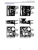
Page 212: ...5 26 DMC III Mechanical Chassis Section 1 1 3 9 5 7 8 6 4 2 3 3 ...

Page 213: ...SETTE NEW 2 XA1 7140 147 000 C 1 SCREW CROSS RECESS PH 3 DA2 2138 000 000 C 4 SCREW NEW 4 DY1 8500 000 000 E 1 DRUM ASS Y NEW 5 DA2 2139 000 000 C 1 WASHER NEW 6 DF1 1703 000 000 C 1 IDLER ASS Y NEW 7 DA2 2116 000 000 C 1 SPRING COIL DRUM NEW 8 DA2 2115 000 000 C 1 SCREW NEW 9 DY1 8501 000 000 B 1 CHASSIS ASS Y SLIDE NEW ...

Page 214: ...5 28 DMC III Mechanical Chassis Section 2 1 2 3 4 5 6 7 8 6 1 9 10 13 11 12 ...

Page 215: ... C 1 BRAKE ASS Y TENSION NEW 5 DF1 1694 000 000 C 1 RELEASE ASS Y TENSION NEW 6 DA2 2139 000 000 C 2 WASHER NEW 7 DF1 1704 000 000 C 1 BRAKE ASS Y S NEW 8 DS1 0199 000 000 C 1 SPRING COIL S BRAKE NEW 9 DG1 4505 000 000 C 1 REEL ASS Y T NEW 10 DA2 2220 000 000 C 1 LEVER EJECT NEW 11 DA2 2238 000 000 C 1 BRAKE MAIN T NEW 12 DS1 0198 000 000 C 1 SPRING COIL T BRAKE NEW 13 DF1 1695 000 000 C 1 REVIEW ...

Page 216: ...5 30 DMC III Mechanical Chassis Section 3 2 2 2 2 2 3 3 8 9 2 10 11 12 13 4 6 7 5 1 ...

Page 217: ... 000 000 C 1 ROLLER ASS Y GUIDE S NEW 5 DF1 1688 000 000 C 1 ROLLER ASS Y GUIDE T NEW 6 DA2 0780 000 000 C 1 SCREW 7 DF1 1686 000 000 C 1 DRUM BASE ASS Y NEW 8 DA2 2259 000 000 C 1 SCREW NEW 9 DG1 4503 000 000 C 1 MOTOR ASS Y CAPSTAN NEW 10 XA1 7140 147 000 C 1 SCREW CROSS RECESS PH 11 DG1 4500 000 000 C 1 ROLLER ASS Y PINCH NEW 12 DA2 2139 000 000 C 1 WASHER NEW 13 DS1 0192 000 000 C 1 SPRING COI...

Page 218: ...5 32 DMC III Mechanical Chassis Section 4 1 3 4 5 8 9 6 10 7 2 ...

Page 219: ... 1 SCREW CROSS RECESS PH 3 DA2 2196 000 000 C 1 BELT TIMING NEW 4 DA2 2197 000 000 C 1 GEAR PULLEY NEW 5 DA2 2190 000 000 C 1 GEAR CONNECT NEW 6 DA2 2140 000 000 C 1 WASHER NEW 7 DA2 2188 000 000 C 1 GEAR WHEEL NEW 8 DA2 2139 000 000 C 1 WASHER NEW 9 DA2 2195 000 000 C 1 GEAR CAPSTAN NEW 10 DG1 4501 000 000 C 1 CHASSIS ASS Y MAIN NEW ...

Page 220: ... WL D79A WL D80A 5 3 N S Product available WIDE ATTACHMENT 6 7 2 1 CG 570 N S Product available CB 570 N S Product available CA 570 N S Product available SDC 8M N S Commercially availabel Make copy sample pictures if necessary PLUG TYPE A JPN E B AS Accessory Section 1 ...

Page 221: ...0 000 C 1 COVER TERMINAL BP 511 BROWN BP 511 512 DY1 8303 000 000 C 1 COVER TERMINAL BP 522 GRAY BP 522 535 5 D83 0622 000 000 C 1 WL 79A WIRELESS CONTROLLER ZR70 MC A ZR65 MC A D83 0652 000 000 C 1 WL 80A WIRELESS CONTROLLER ZR60A 6 DY1 8528 000 000 C 1 COVER BATTERY WL D79A DY1 8121 000 000 C 1 COVER BATTERY WL D80A 7 DY1 8530 000 000 C 1 LABEL WIRELESS CONTROLLER A WL D79A DY1 8119 000 000 C 1 ...

Page 222: ...ZR60 A 6 SS 800 WD 30 5 TL 30 5 2 1 DM 50 N S Product available N S Product available N S Product available 5 4 5 4 3 VL 3 N S Product available FS 30 5 N S Product available N S Product available IFC 300PCU Accessory Section 2 ...

Page 223: ...70 MC A ZR65 MC A ZR60 A 1 DY1 8246 000 000 C 1 WIND SCREEN FRONT 2 DY1 8247 000 000 C 1 WIND SCREEN REAR 3 DY1 8245 000 000 E 1 LAMP HAROGEN 4 DY4 4764 000 000 C 1 CAP CONVERTER FRONT 5 DY4 4765 000 000 C 1 CAP CONVERTER REAR 6 D81 1430 000 000 C 1 SHOULDER STRAP SS 800 ...

Page 224: ...4 FU3205 only with same type 494001 1 0A 50V FUSE and replace FU3202 FU3203 only same type 49401 5 1 5A 50V FUSE MANUFACTURER LITTELFUSE CN891 CN303 CN302 CN300 CN301 CN102 CN101 CN100 CN3202 CN3201 CN2000 CN2101 IC300 IC301 IC102 IC103 IC3204 IC100 IC1802 IC2100 CN990 CN2900 CN1101 CN2501 MAIN P C B FU3205 FU1801 FU3201 FU3202 FU3204 FU3203 ...

Page 225: ...1 WS1 6098 000 000 C 1 CONNECTOR DV NEW FU1801 VD7 2241 001 000 C 1 CHIP FUSE FU3201 VD7 2241 001 000 C 1 CHIP FUSE FU3202 VD7 2241 501 000 C 1 CHIP FUSE FU3203 VD7 2241 501 000 C 1 CHIP FUSE FU3204 VD7 2241 001 000 C 1 CHIP FUSE FU3205 VD7 2241 001 000 C 1 CHIP FUSE CAC P C B ASS Y CN1001 VS1 6228 015 000 C 1 CONNECTOR 15p NEW CN1201 VS1 6851 021 000 C 1 CONNECTOR 21p CN1501 VS1 6851 023 000 C 1 ...

Page 226: ...AM NEW 33 DA2 2195 000 000 C 1 GEAR CAPSTAN NEW 33 DA2 2196 000 000 C 1 BELT TIMING NEW 33 DA2 2197 000 000 C 1 GEAR PULLEY NEW 29 DA2 2220 000 000 C 1 LEVER EJECT NEW 29 DA2 2238 000 000 C 1 BRAKE MAIN T NEW 31 DA2 2259 000 000 C 1 SCREW NEW 31 DA2 2261 000 000 C 8 SCREW NEW 21 DA3 0160 000 000 C 1 HOLDER RECORDER NEW 21 DA3 0161 000 000 C 1 SHIELD CASE HA NEW 21 DA3 0162 000 000 C 1 SHIELD CASE ...

Page 227: ...274 000 000 B 1 COVER L JACK ZR70 MC A ZR65 MC A NEW 5 DA3 0281 000 000 B 1 COVER L JACK ZR60 A NEW 15 DA3 0284 000 000 B 1 COVER LCD TOP ZR65 MC A NEW 15 DA3 0287 000 000 B 1 COVER LCD TOP ZR60 A NEW 9 DA3 0294 000 000 B 1 COVER LEFT ZR65 MC A NEW 9 DA3 0296 000 000 B 1 COVER LEFT ZR60 A NEW 3 DA3 0299 000 000 C 1 CUSHION NEW 9 DA3 0301 000 000 C 1 LABEL NAME ZR70 MC A NEW 9 DA3 0303 000 000 C 1 ...

Page 228: ...00 C 1 RECORDER UNIT DMC III 27 DY1 8500 000 000 E 1 DRUM ASS Y NEW 27 DY1 8501 000 000 B 1 CHASSIS ASS Y SLIDE NEW 9 DY1 8502 000 000 C 1 PCB ASS Y EJECT NEW 5 DY1 8503 000 000 B 1 COVER ASS Y F JACK ZR70 MC A NEW 5 DY1 8504 000 000 B 1 LENS RING ASS Y ZR70 MC A NEW 13 DY1 8505 000 000 B 1 COVER ASS Y RIGHT ZR70 MC A NEW 15 DY1 8507 000 000 B 1 HINGE ASS Y NEW 23 DY1 8508 000 000 B 1 CCD ASS Y NE...

Page 229: ... C 1 JACK S VIDEO NEW 3 XA1 3170 507 000 F 4 SCREW 27 31 33 XA1 7140 147 000 C 3 SCREW CROSS RECESS PH 13 XA1 7170 207 000 F 5 4 SCREW ZR65 MC A ZR60 A 9 XA1 7170 257 000 F 5 SCREW 3 7 15 19 21 XA1 7170 307 000 F 29 SCREW 3 11 XA1 7170 407 000 F 4 SCREW 7 13 XA4 7170 407 000 F 2 1 SCREW ZR65 MC A ZR60 A 25 XA4 9170 357 000 F 2 SCREW 13 17 XA4 9170 407 000 F 9 SCREW 7 9 XA4 9170 409 000 F 5 SCREW 3...

Page 230: ...MS CONTENTS INTERCONNECTION DIAGRAM BLOCK DIAGRAMS CAMERA SECTION 1 CAMERA SECTION 2 SYSTEM CONTROL SECTION SERVO SECTION AUDIO VIDEO SECTION 1 AUDIO VIDEO SECTION 2 POWER SUPPLY SECTION LCD P C B SECTION JACK P C B SECTION ...

Page 231: ... IC1802 IC2100 CN990 CN1101 CN2501 1 1 1 1 1 1 1 6 1 3 1 2 33 32 10 A1 B1 A15 B15 1 7 10 11 18 21 1 1 A1 B1 A35 B35 12 39 9 CN701 IC801 IC802 IC803 IC3203 IC3202 IC2300 IC1102 IC2301 IC2000 IC2302 IC3201 IC1101 1 4 CN1201 IC1701 IC1002 IC1502 CN1001 CN1501 1 1 1 2 23 22 CN4101 22 23 2 1 15 2 21 20 CN1502 1 7 IC1001 IC1202 IC1501 CN1002 A1 B1 A35 B35 CN1 IC1601 IC1602 CN2 CN3 CN4 CN5 CN7 2 1 1 2 39...

Page 232: ... 7 8 9 10 11 12 13 14 15 16 17 18 19 20 21 22 23 24 LCD EEP SOUT LCD EEP SCK SIN1 C SYNC PANEL R PANEL G PANEL B LCD 3V LCD 5V LCD 8 5V LCD 15V LCD 10V GND MO GND VTR UNREG PANEL XOE PANEL LCK LCD CS LCD EEP CS VGL N C STVR U D CKV DEV STVL VCC VGH VCOM AVDD STHR L R N C VR VG VB GND CPH3 CPH2 CPH1 Q1H OEH STHL LCD P C B CN1070 1 2 3 4 5 6 7 8 9 10 11 12 13 14 15 GND CCD OUT GND VL 7 5V VH 15V GND...

Page 233: ...5 6 7 3 2 1 4 VSUB V 2 V 1 V 3 V 4 CCD VH 15V CCD VL 7 5V RESET H 1 H 2 CCD OUT CN1001 1 2 3 4 5 11 12 7 8 9 14 TO LENS UNIT XSTH STH CKH1 CKH2 G R B DSG XDSG ENB XENB XSTV STV CKV2 CKV1 COM DSD VDD VBB BL5V BL5V CN1501 1 2 3 5 7 8 9 11 12 15 16 17 18 19 20 21 13 6 14 22 23 FOCUS A FOCUS B FOCUS B FOCUS A ZOOM B ZOOM B ZOOM A ZOOM A DRIVE DRIVE HALL IN HALL OUT HALL IN HALL OUT FOCUS VCC ZOOM SENS...

Page 234: ...64 MDATA L5 229 MDATA L6 150 MDATA L7 299 MDATA L8 228 MDATA L9 149 MDATA L10 62 MDATA L11 298 MDATA L12 227 MDATA L13 61 MDATA L14 297 MDATA L15 226 MDATA L16 147 MDATA L17 60 MDATA L18 59 MDATA L19 146 MDATA L20 58 MDATA L21 145 MDATA L22 295 MDATA L23 224 MDATA L24 57 MDATA L25 223 MDATA L26 294 MDATA L27 56 MDATA L28 143 MDATA L29 222 MDATA L30 55 MDATA L31 96 RAWDATA 2 4 RAWDATA 3 255 RAWDATA...

Page 235: ...TERY CK 3V PHOTO SW HALF PHOTO SW START STOP SW TAPE CARD SW VTR PW SW CAM PW SW ZOOM AD CN101 1 4 5 8 6 9 10 2 DVDD3V E3V LI3V EPM CE CNVSS FLASH CLK FLASH RST FLASH RXD1 FLASH TXD1 MODE RESET DEBCLK DEBUD DEBDD XDEBEN CG CS EEP CG CLK EEP CG SO DOT CLK OSD I0 OSD I1 VIC HD VIC VD VIC VD VIC HD OSD I1 OSD I0 DOT CLK EEP CG SO EEP CG CLK CGCS XDEBEN DEBDD DEBUD DEBCLK ZOOM KEY VTR POW SW CAM POW S...

Page 236: ...EF 57 D PS 58 C PS 59 C FBR 62 C EC 61 C VS 37 35 34 33 D COM D U D V D W 3 1 2 7 OUT 2 6 IN 2 5 IN 2 IN 1 OUT 1 IN 1 20 19 18 D FGIN D FGPGIN D PGIN 12 C HW 11 C HW 10 C HU 9 C HU 8 C HV 7 C HV 44 L REV 42 L FWD 46 R IN1 47 R IN1 49 R IN2 50 R IN2 2 C U 3 C V 5 C W D VM D VS C VS CFG DPG DFG CFG DPG DFG DERR LOAD FR LODE ON DRUM ON CAP ON CAP FWD CERR T REEL FG S REEL FG DA CFG DEW MSW AD TAPE TO...

Page 237: ...IDE DETECT Q2103 Q2101 Q2106 Q2105 Q2100 Q2102 AVDD 1 4V MIC R L RMC IN EJECT SW S DET LET CONT WIDE CONT LINE IN X RESET MIC2 MIC3 ADV MIC L ADV MIC R SHOE ID1 SHOE ON EADDR 0 EADDR 6 EADDR 7 EADDR 8 EADDR 9 EADDR 10 EADDR 11 EADDR 12 EADDR 13 EADDR 14 EADDR 15 EADDR 16 EADDR 17 EADDR 18 EADDR 19 EADDR 20 EADDR 1 EADDR 2 EADDR 3 EADDR 4 EADDR 5 TO CAMERA SECTION 2 MAIN P C B FROM AUDIO VIDEO SECT...

Page 238: ...S XCAS XWE DQML ADDR 13 ADDR 12 ADDR 11 ADDR 10 ADDR 9 ADDR 8 ADDR 7 ADDR 6 ADDR 5 ADDR 4 ADDR 3 ADDR 2 ADDR 1 ADDR 0 MDATA 15 MDATA 14 MDATA 13 MDATA 12 MDATA 11 MDATA 10 MDATA 9 MDATA 8 MDATA 7 MDATA 6 MDATA 5 MDATA 4 MDATA 3 MDATA 2 MDATA 1 MDATA 0 XTPB TPB XTPA TPA H1B 2 CN2000 H1A 3 H2A 5 H2B 6 CH 1 HEAD DRUM UNIT CH 2 HEAD CN2501 TO DV TERMINAL TO SYSTEM CONTROL SECTION MAIN P C B GDH CONT E...

Page 239: ...M 3V LPF IRIS 3V LPF HA 3V LCD 3V ON OFF CONT CH1 3 4 8 CH2 CH5 6 CH7 D VM C VS SHOE UNREG SHOE UNREG ID 1 ADV MIC L ADV MIC R CN891 1 2 5 8 9 C VS D VS ADV MIC R ADV MIC L SHOE ID1 SHOE ON TO SYSTEM CONTROL SECTION MAIN P C B TO SHOE CONNECTOR ASS Y TO AUDIO VIDEO SECTION 1 MAIN P C B TO SYSTEM CONTROL SECTION MAIN P C B 4 3 2 1 5 7 8 T3201 4 3 2 1 5 7 8 T3202 D3201 Q3202 Q3201 Q3200 D3202 D3204 ...

Page 240: ...MP CNTRST GAMMA S H IC903 AN2545NFHQ LCD DRIVE 37 47 1 34 8 9 18 43 25 44 33 32 31 30 29 24 23 22 20 19 39 38 48 2 11 14 16 Q910 5V ON LCD 5V VG CN903 VB L R STHR STHL 22 23 10 6 9 5 7 3 21 20 19 24 12 13 17 16 VR 15 AVDD 11 VCC 8 VGL 1 L CS CLK SO CS BRIGHT R OUT G OUT B OUT G CLAMP GCA GCA GCA B CLK CONTROL D1 VCC2 VDD VCC3 VCC1 STH2 41 RL STH1 CPH3 CPH2 CPH1 STV1 STV2 CPV OEV QH OEH COMDC VCOM ...

Page 241: ...IN EJECT SW S DET Y I O C I O P GY OUT Y GY OUT 18 17 31 37 36 35 25 27 28 24 16 13 12 20 8 6 5 2 21 9 CN5 SP SP 1 2 CN2 CN1 MIC JACK AV JACK VBUS 5V D D CN3 1 2 3 EJECT SW CN6 2 TO EJECT SW CN4 S JACK SPEAKER CAM3V CAM3V TO AUDIO VIDEO SECTION 1 MAIN P C B CN2101 TO CAMERA SECTION 2 MAIN P C B CN2101 USB JACK JACK P C B ZR70 MC A ZR65MC DM MV650i E DM MV630i E DM FV40 ONLY JACK P C B SECTION ZR70...

Reviews: