


ZR70 MC A, ZR65 MC A, ZR60 A
CHAPTER 4. DISASSEMBLING ADJUSTMENT
4-9
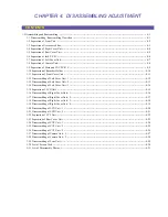
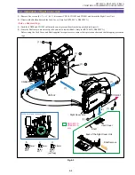
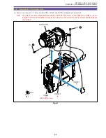
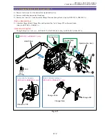
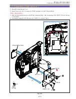
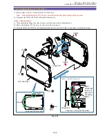
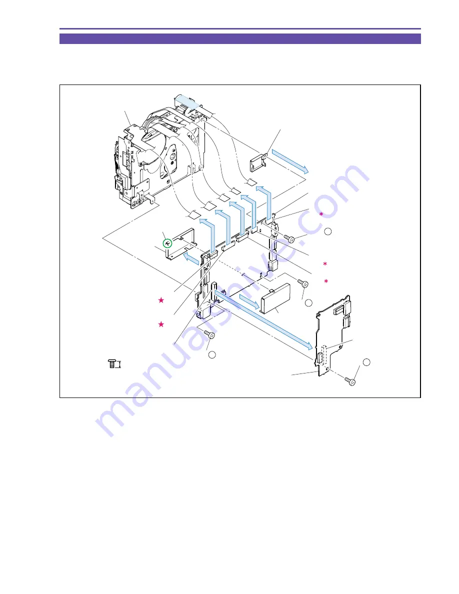
1-9 Separation of Main and CAC P.C.B.'s
(1) Remove one screw (b
×
1), disconnect the CN1101 and CN1002 (B to B) and detach the CAC P.C.B.
(2) Remove three screws (b
×
3), disconnect the CN300, CN301, CN302, CN303, and CN2000 and detach the MAIN P.C.B.
(3) Detach the soldered part on the PM Shield 1 and detach the HA Shield and PM Shield 1 and 2.
Fig. 4-8
CN301
HA Shield
MAIN P.C.B.
CAC P.C.B.
PM
Shield 2
PM
Shield 1
Solder
DMC III
CN303
CN1101
(B to B)
CN302
(1)
(3)
(3)
(2)
CN2000
CN300
CN1002
(B to B)
(1) - b
(2) - b
(2) - b
(2) - b
(2)
3mm
Metal
M1.7
b
Summary of Contents for ZR70 MC A
Page 12: ...ZR70 MC A ZR65 MC A ZR60 A CHAPTER 1 GENERAL DESCRIPTION OF PRODUCT 1 9 External View Fig 1 1 ...
Page 190: ...5 4 ZR70 MC A ZR65 MC A ZR60 A Front Cover Unit Section 4 1 2 6 7 8 3 2 5 3 3 ...
Page 194: ...5 8 ZR70 MC A ZR65 MC A ZR60 A Left Cover Unit Section 2 7 3 2 2 2 2 8 2 5 7 6 9 1 3 4 A A ...
Page 200: ...5 14 ZR70 MC A ZR65 MC A ZR60 A LCD Unit Section 1 3 2 1 3 4 5 10 2 6 7 9 8 ...
Page 202: ...5 16 ZR70 MC A ZR65 MC A ZR60 A Rear Cover Unit Section 7 4 1 1 3 5 8 6 8 4 2 CVF Unit 1 3 ...
Page 210: ...5 24 ZR70 MC A ZR65 MC A ZR60 A Lens Unit Section 3 2 10 4 5 7 9 8 7 8 1 3 6 2 6 2 ...
Page 212: ...5 26 DMC III Mechanical Chassis Section 1 1 3 9 5 7 8 6 4 2 3 3 ...
Page 214: ...5 28 DMC III Mechanical Chassis Section 2 1 2 3 4 5 6 7 8 6 1 9 10 13 11 12 ...
Page 216: ...5 30 DMC III Mechanical Chassis Section 3 2 2 2 2 2 3 3 8 9 2 10 11 12 13 4 6 7 5 1 ...
Page 218: ...5 32 DMC III Mechanical Chassis Section 4 1 3 4 5 8 9 6 10 7 2 ...


