


ZR70 MC A, ZR65 MC A, ZR60 A
CHAPTER 4. DISASSEMBLING ADJUSTMENT
4-11
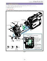
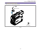
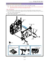
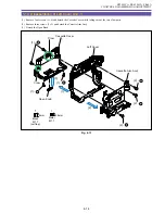
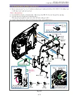
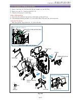
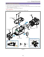
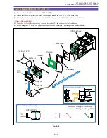
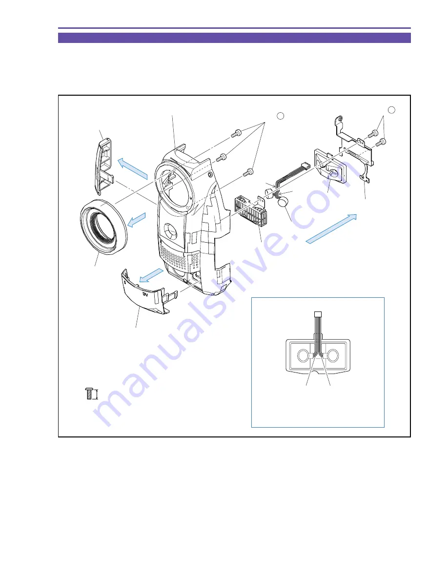
1-11 Separation of Front Cover Unit
(1) Remove three screws (d
×
3) and detach the Lens Cover, L Jack Cover and F Jack Cover.
(2) Remove two screws (d
×
2) and detach the Microphone Cover, Rubber, Microphone Ass'y and Microphone Shield.
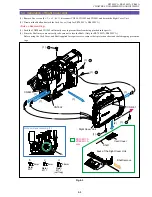
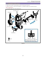
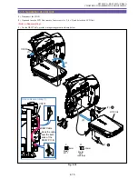
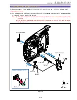
<Note on Reassembling>
(1) Treat the Microphone Ass'y Cable as illustrated below.
Fig. 4-10
Note on Reassembling (1)
(1)
(2)
(1)
(1)
Lens Cover
MIC Shield
F Jack Cover
L Jack Cover
Front Cover Unit
MIC Holder
MIC Ass'y
Rubber
Black/
White
Black/
Red
Take care to make the four cables come
out of the front cover in line so as to
prevent them from crossing each other.
Black/Red
Black/White
(1) - d
(2) - d
4.5mm
Metal
M1.7
(self tap)
d
Summary of Contents for ZR70 MC A
Page 12: ...ZR70 MC A ZR65 MC A ZR60 A CHAPTER 1 GENERAL DESCRIPTION OF PRODUCT 1 9 External View Fig 1 1 ...
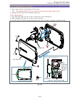
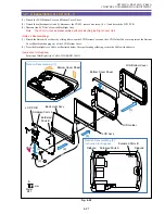
Page 190: ...5 4 ZR70 MC A ZR65 MC A ZR60 A Front Cover Unit Section 4 1 2 6 7 8 3 2 5 3 3 ...
Page 194: ...5 8 ZR70 MC A ZR65 MC A ZR60 A Left Cover Unit Section 2 7 3 2 2 2 2 8 2 5 7 6 9 1 3 4 A A ...
Page 200: ...5 14 ZR70 MC A ZR65 MC A ZR60 A LCD Unit Section 1 3 2 1 3 4 5 10 2 6 7 9 8 ...
Page 202: ...5 16 ZR70 MC A ZR65 MC A ZR60 A Rear Cover Unit Section 7 4 1 1 3 5 8 6 8 4 2 CVF Unit 1 3 ...
Page 210: ...5 24 ZR70 MC A ZR65 MC A ZR60 A Lens Unit Section 3 2 10 4 5 7 9 8 7 8 1 3 6 2 6 2 ...
Page 212: ...5 26 DMC III Mechanical Chassis Section 1 1 3 9 5 7 8 6 4 2 3 3 ...
Page 214: ...5 28 DMC III Mechanical Chassis Section 2 1 2 3 4 5 6 7 8 6 1 9 10 13 11 12 ...
Page 216: ...5 30 DMC III Mechanical Chassis Section 3 2 2 2 2 2 3 3 8 9 2 10 11 12 13 4 6 7 5 1 ...
Page 218: ...5 32 DMC III Mechanical Chassis Section 4 1 3 4 5 8 9 6 10 7 2 ...


