


ZR70 MC A, ZR65 MC A, ZR60 A
CHAPTER 4. DISASSEMBLING ADJUSTMENT
4-21
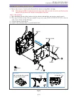
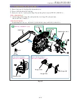
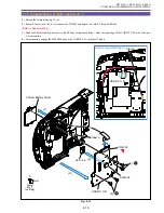
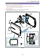
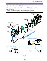
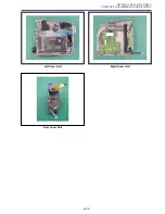
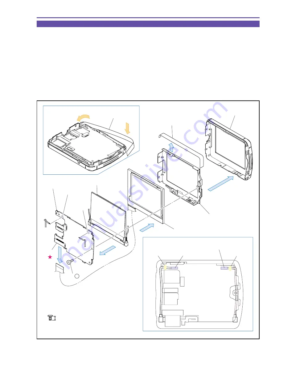
1-21 Disassembling of LCD Unit - 2
(1) Detach the LCD Bottom Cover and Bottom Cover Sheet.
(2) Detach the soldered parts A and B, disconnect the CN903, remove one screw (b
×
1) and detach the LCD P.C.B.
(3) Demount the LCD Ass'y from the Backlight Ass'y.
Note : The LCD Unit can be disassembled without detaching the Right Cover Unit.
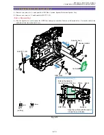
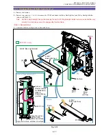
<Note on Reassembling>
(1) Detach the Bottom Cover Sheet by sliding it between the LCD Bottom Cover and the LCD Holder. Take care to prevent the Bottom
Cover Sheet from hanging out of the LCD Bottom Cover.
(2) Treat the Backlight Ass'y Cable as illustrated below. After performing soldering, secure the Cable with adhesive.
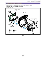
<Instruction for Supplies>
Securing of Backlight Ass'y Cable : DIA BOND 1663G
Fig. 4-20
Note on Reassembling (1)
Note on Reassembling (2)
Instruction for Supplies
CN903
(2)
(2)
(1)
(3)
(1)
LCD Ass'y
Back Light Ass'y
LCD P.C.B.
Soldered Parts A
Soldered
Parts B
LCD Holder
Bottom Cover Sheet
Bottom Cover Sheet
LCD Bottom Cover
Soldered Parts A
Soldered Parts B
Diabond
Diabond
(2) - b
3mm
Metal
M1.7
b
Summary of Contents for ZR70 MC A
Page 12: ...ZR70 MC A ZR65 MC A ZR60 A CHAPTER 1 GENERAL DESCRIPTION OF PRODUCT 1 9 External View Fig 1 1 ...
Page 190: ...5 4 ZR70 MC A ZR65 MC A ZR60 A Front Cover Unit Section 4 1 2 6 7 8 3 2 5 3 3 ...
Page 194: ...5 8 ZR70 MC A ZR65 MC A ZR60 A Left Cover Unit Section 2 7 3 2 2 2 2 8 2 5 7 6 9 1 3 4 A A ...
Page 200: ...5 14 ZR70 MC A ZR65 MC A ZR60 A LCD Unit Section 1 3 2 1 3 4 5 10 2 6 7 9 8 ...
Page 202: ...5 16 ZR70 MC A ZR65 MC A ZR60 A Rear Cover Unit Section 7 4 1 1 3 5 8 6 8 4 2 CVF Unit 1 3 ...
Page 210: ...5 24 ZR70 MC A ZR65 MC A ZR60 A Lens Unit Section 3 2 10 4 5 7 9 8 7 8 1 3 6 2 6 2 ...
Page 212: ...5 26 DMC III Mechanical Chassis Section 1 1 3 9 5 7 8 6 4 2 3 3 ...
Page 214: ...5 28 DMC III Mechanical Chassis Section 2 1 2 3 4 5 6 7 8 6 1 9 10 13 11 12 ...
Page 216: ...5 30 DMC III Mechanical Chassis Section 3 2 2 2 2 2 3 3 8 9 2 10 11 12 13 4 6 7 5 1 ...
Page 218: ...5 32 DMC III Mechanical Chassis Section 4 1 3 4 5 8 9 6 10 7 2 ...


