


ZR70 MC A, ZR65 MC A, ZR60 A
CHAPTER 4. DISASSEMBLING ADJUSTMENT
4-23
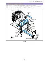
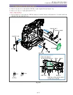
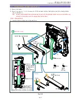
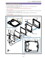
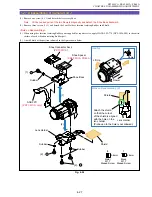
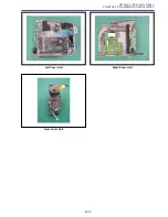
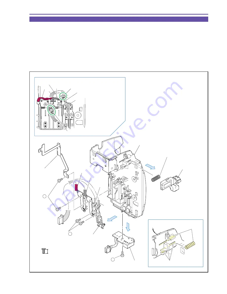
1-23 Separation of Rear Cover Unit
(1) Remove four screws (h
×
4) and detach the Battery Terminal Ass'y and GND Plate.
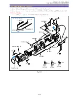
(2) Remove one screw (h
×
1) and detach the DC P.C.B.
(3) Detach the Battery Eject Lever and Sring.
<Note on Reassembling>
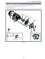
(1) Secure the cables of Battery Terminal Ass'y with the hooks as illustrated below.
(2) When attaching the Battery Terminal Ass'y, screw the Red, Black, White and Gray cables in this order.
<Instruction for Supplies>
Rear Cover, Spring : Apply HANAL FL-778. (DY9-3026-000)
Fig. 4-22
Note on Reassembling (1)
Instruction for Supplies
GND Plate
(1)
Red
Black
Battery Terminal
Ass'y
Rear Cover
(2)
(3)
White
Gray
Spring
Battery Eject Lever
(1) - h
(1) - h
(2) - h
Black
White
Gray
Red
Secure the cables with the hooks.
Secure the cables with the hooks.
Hanal FL-778
Hanal FL-778
DC P.C.B.
4mm
Metal
M1.7
(self tap)
h
Summary of Contents for ZR70 MC A
Page 12: ...ZR70 MC A ZR65 MC A ZR60 A CHAPTER 1 GENERAL DESCRIPTION OF PRODUCT 1 9 External View Fig 1 1 ...
Page 190: ...5 4 ZR70 MC A ZR65 MC A ZR60 A Front Cover Unit Section 4 1 2 6 7 8 3 2 5 3 3 ...
Page 194: ...5 8 ZR70 MC A ZR65 MC A ZR60 A Left Cover Unit Section 2 7 3 2 2 2 2 8 2 5 7 6 9 1 3 4 A A ...
Page 200: ...5 14 ZR70 MC A ZR65 MC A ZR60 A LCD Unit Section 1 3 2 1 3 4 5 10 2 6 7 9 8 ...
Page 202: ...5 16 ZR70 MC A ZR65 MC A ZR60 A Rear Cover Unit Section 7 4 1 1 3 5 8 6 8 4 2 CVF Unit 1 3 ...
Page 210: ...5 24 ZR70 MC A ZR65 MC A ZR60 A Lens Unit Section 3 2 10 4 5 7 9 8 7 8 1 3 6 2 6 2 ...
Page 212: ...5 26 DMC III Mechanical Chassis Section 1 1 3 9 5 7 8 6 4 2 3 3 ...
Page 214: ...5 28 DMC III Mechanical Chassis Section 2 1 2 3 4 5 6 7 8 6 1 9 10 13 11 12 ...
Page 216: ...5 30 DMC III Mechanical Chassis Section 3 2 2 2 2 2 3 3 8 9 2 10 11 12 13 4 6 7 5 1 ...
Page 218: ...5 32 DMC III Mechanical Chassis Section 4 1 3 4 5 8 9 6 10 7 2 ...


