


ZR70 MC A, ZR65 MC A, ZR60 A
CHAPTER 4. DISASSEMBLING ADJUSTMENT
4-29
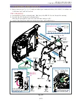
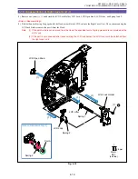
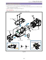
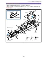
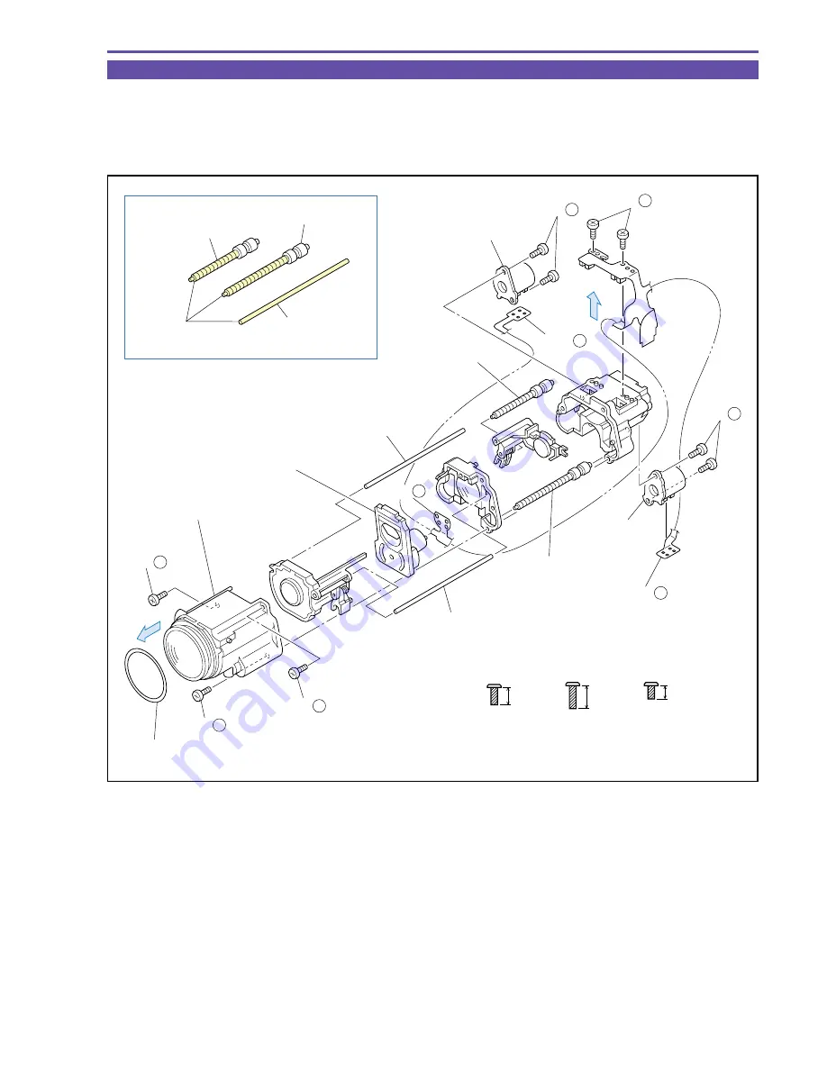
1-29 Disassembling of Lens Unit
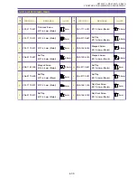
(1) Remove the Lens Rubber part and three screws (m
×
3). Demount the Front Lens Ass'y.
(2) Remove six screws (d
×
4, n
×
2) and solder (
α
). Demount the PZ Motor, AF Motor, IG Meter Ass'y, PZ Shaft, and AF Shaft.
<Instruction for Supply>
On the AF/PZ Shaft and Guide Bar : LOGENEST LAMBDA A-74 (CY9-8102-000)
Fig. 4-28
4.5mm
Metal
M1.7
(self tap)
d
6mm
Metal
M1.7
(self tap)
m
3.5mm
Metal
M1.7
(self tap)
n
Instruction for Supply
PZ Shaft
PZ Shaft
AF Shaft
AF Shaft
PZ Motor
IG Meter Ass'y
AF Motor
Gide Bar
Front Lens Ass'y
LOGENEST LAMBDA
A-74
Lens Rubber
Gide Bar
Guide Bar × 2
(1)
(2) -
α
(2) -
α
(2) -
α
(2)
(2)
(2) - d
(2) - d
(2) - n
(1) - m
(1) - m
(1) - m
Summary of Contents for ZR70 MC A
Page 12: ...ZR70 MC A ZR65 MC A ZR60 A CHAPTER 1 GENERAL DESCRIPTION OF PRODUCT 1 9 External View Fig 1 1 ...
Page 190: ...5 4 ZR70 MC A ZR65 MC A ZR60 A Front Cover Unit Section 4 1 2 6 7 8 3 2 5 3 3 ...
Page 194: ...5 8 ZR70 MC A ZR65 MC A ZR60 A Left Cover Unit Section 2 7 3 2 2 2 2 8 2 5 7 6 9 1 3 4 A A ...
Page 200: ...5 14 ZR70 MC A ZR65 MC A ZR60 A LCD Unit Section 1 3 2 1 3 4 5 10 2 6 7 9 8 ...
Page 202: ...5 16 ZR70 MC A ZR65 MC A ZR60 A Rear Cover Unit Section 7 4 1 1 3 5 8 6 8 4 2 CVF Unit 1 3 ...
Page 210: ...5 24 ZR70 MC A ZR65 MC A ZR60 A Lens Unit Section 3 2 10 4 5 7 9 8 7 8 1 3 6 2 6 2 ...
Page 212: ...5 26 DMC III Mechanical Chassis Section 1 1 3 9 5 7 8 6 4 2 3 3 ...
Page 214: ...5 28 DMC III Mechanical Chassis Section 2 1 2 3 4 5 6 7 8 6 1 9 10 13 11 12 ...
Page 216: ...5 30 DMC III Mechanical Chassis Section 3 2 2 2 2 2 3 3 8 9 2 10 11 12 13 4 6 7 5 1 ...
Page 218: ...5 32 DMC III Mechanical Chassis Section 4 1 3 4 5 8 9 6 10 7 2 ...


