


ZR70 MC A, ZR65 MC A, ZR60 A
CHAPTER 4. DISASSEMBLING ADJUSTMENT
4-33
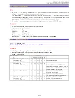
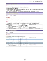
2. Adjustment Procedures
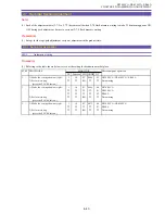
2-1 Adjustment Items in Part Replacement
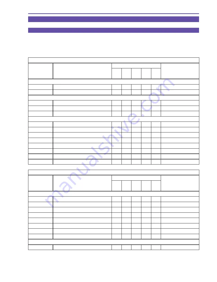
After replacement of major parts, carry out adjustment referring to the table shown below. Note that the following table shows minimum
required adjustments to be performed after replacing any major part. In case that two or more parts have been replaced or any faulty
condition has occurred, take a proper adjustment procedure accordingly.
○
: Adjustment required
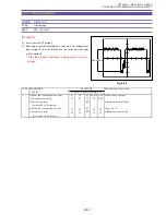
Camera system
Part name
No.
Adjustment item
Lens
JACK
PCB
CCD
MAIN
PCB
CAC
PCB
Adjustment setting
2-2 AF section
2-2-1
CZ Automatic Adjustment
○
○
○
Product condition
2-2-2
Cam correction (AUT O)
○
○
○
Product condition
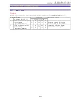
2-3 IS section
2-3-1
Gyro Offset Adjustment
○
○
○
Product condition
2-3-2
Gyro Gain Adjustment
○
○
Product condition
2-3-3
Virtual EEPROM and Flash Memory Writing
○
○
○
Product condition
2-4 Camera section
2-4-1
Iris Adjustment
○
○
○
○
Product condition
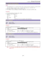
2-4-2
WB Adjustment (1)
○
○
○
○
Product condition
2-4-3
Color Balance Adjustment
○
○
○
○
Product condition
2-4-4
WB Adjustment (2)
○
○
○
○
Product condition
2-4-5
WB Adjustment (3)
○
○
○
○
Product condition
2-4-6
Virtual EEPROM and Flash Memory Writing
○
○
○
○
Product condition
2-5
CCD Pixel Missing Compensation
○
○
Product condition
2-6
Color Balance Check
○
○
○
Product condition
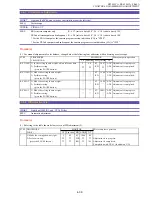
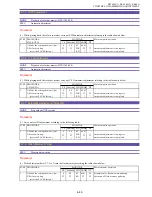
Recorder system
Part name
No.
Adjustment item
MAIN
PCB
CAC
PCB
DMC
III
Adjustment setting
2-7 Recorder section
2-7-1
Setting for Destination
○
Product condition
2-7-2, 2-7-3
Y LEVEL / C LEVEL Adjustment
○
Product condition
2-7-4
AGC Initial Value Adjustment
○
Product condition
2-7-5
SWP Adjustment
○
○
Product condition
2-7-6
C. FG Adjustment
○
○
Product condition
2-7-7
Automatiac Adjustment of Reel FG
○
○
2-7-8
Flash Memory Writing
○
○
2-7-9
Battery Voltage Drop Adjustment
○
○
Product condition
DMC III
2-8
T ape Path Adjustment
T ape path adjustment setting
Summary of Contents for ZR70 MC A
Page 12: ...ZR70 MC A ZR65 MC A ZR60 A CHAPTER 1 GENERAL DESCRIPTION OF PRODUCT 1 9 External View Fig 1 1 ...
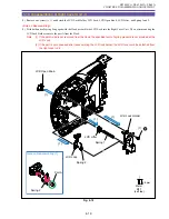
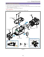
Page 190: ...5 4 ZR70 MC A ZR65 MC A ZR60 A Front Cover Unit Section 4 1 2 6 7 8 3 2 5 3 3 ...
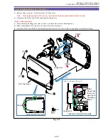
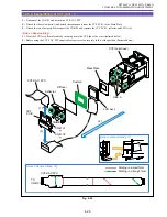
Page 194: ...5 8 ZR70 MC A ZR65 MC A ZR60 A Left Cover Unit Section 2 7 3 2 2 2 2 8 2 5 7 6 9 1 3 4 A A ...
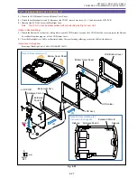
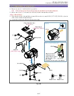
Page 200: ...5 14 ZR70 MC A ZR65 MC A ZR60 A LCD Unit Section 1 3 2 1 3 4 5 10 2 6 7 9 8 ...
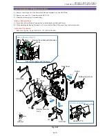
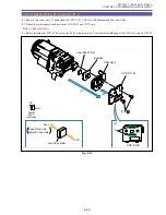
Page 202: ...5 16 ZR70 MC A ZR65 MC A ZR60 A Rear Cover Unit Section 7 4 1 1 3 5 8 6 8 4 2 CVF Unit 1 3 ...
Page 210: ...5 24 ZR70 MC A ZR65 MC A ZR60 A Lens Unit Section 3 2 10 4 5 7 9 8 7 8 1 3 6 2 6 2 ...
Page 212: ...5 26 DMC III Mechanical Chassis Section 1 1 3 9 5 7 8 6 4 2 3 3 ...
Page 214: ...5 28 DMC III Mechanical Chassis Section 2 1 2 3 4 5 6 7 8 6 1 9 10 13 11 12 ...
Page 216: ...5 30 DMC III Mechanical Chassis Section 3 2 2 2 2 2 3 3 8 9 2 10 11 12 13 4 6 7 5 1 ...
Page 218: ...5 32 DMC III Mechanical Chassis Section 4 1 3 4 5 8 9 6 10 7 2 ...


