Page 4
CNPx-50
INSTALLATION GUIDE
#44-000017
Updated 0
4
.
2
0.1
8
US LED | 6807 PORTWEST DR | HOUSTON, TX 77024 | T 866 972 9191 | F 713 972 9393 | info@usled.com | www.usled.com
1. Turn off main power.
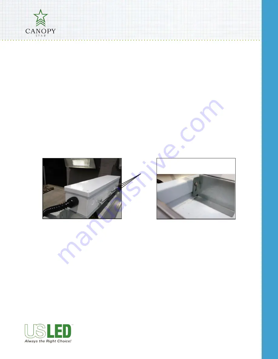
2. Secure driver box assembly to mounting bracket by tightening mounting screws using ¼” hex driver.
See Figure 9.
3. Secure mounting bracket to any vertical wall using #10 sheet metal screws supplied. Insure location allows wire
harness to reach low voltage side of power supply box. See Figure 10.
4. Make internal primary side (high voltage) power connections by connecting wires, Black to Load, White to Neu-
tral and Green to Ground using approved electrical connector. See wire diagrams.
5. Make secondary (low voltage) connections by using approved electrical connector. See wire diagrams.
6. Secure driver box top using #8 sealing machine screws supplied.
7. Turn on power.
INSTALLATION INSTRUCTIONS - DRIVER BOX
FIG 9
FIG 10
Mounting screws


