5
1. Power down the machine.
2. Remove the bill acceptor.
3. Remove the POS window above the bill
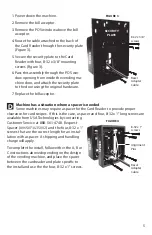
acceptor.
4. Route the cable attached to the back of
the Card Reader through the security plate
(Figure 3).
5. Secure the security plate to the Card
Reader with four, 8-32 x 3/8” mounting
screws (Figure 3).
6. Pass this assembly through the POS win-
dow opening from inside the vending ma-
chine door, and attach the security plate
to the door using the original hardware.
7. Replace the bill acceptor.
Machine has a situation where a spacer is needed
Some machines may require a spacer for the Card Reader to provide proper
clearance for card swipes. If this is the case, a spacer and four, 8-32 x 1” long screws are
available from USA Technologies by contacting
Customer Service at 888-561-4748. Request
Spacer (#
V6SUF1435002
) and the four, 8-32 x 1”
screws that are the correct length for an instal-
lation with a spacer. A shipping and handling
charge will apply.
To complete the install, follow either the A, B or
C instructions above depending on the design
of the vending machine, and place the spacer
between the cardreader and plate specifi c to
the install and use the the four, 8-32 x 1” screws.
D
8-32 x 1”
screws
Alignment
Pins
SP
A
CER
READER
FIGURE 4
Bezel
Adapter
Cable
8-32 x 3/8”
screws
SECURITY
PLATE
READER
FIGURE 3
Bezel
Adapter
Cable


