37
© 2021, Elon Group AB. All rights reserved.
PREPARATION
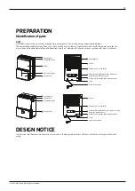
Identification of parts
NOTE:
All the illustrations in the manual are for explanatory purposes only. Your machine may appear slightly different.
The overall shape will be the same. The unit can be controlled by using the unit control panel alone or with the remote controller. This
manual does not include Remote Controller Operations, see the << Remote Controller Instruction >> packed with the unit for details.
DESIGN NOTICE
In order to ensure the optimal performance of our products, the design specifications of the unit are subject to change without prior
notice.
Water bucket
Air outlet grille
Control panel
Handle (both sides)
Water bucket
Air outlet grille
Air filter
Continuous drain hose outlet
Power cord buckle (placed in the water bucket,
used only when storing the unit)
Pump drain hose outlet (some models without)
Caster
Power cord and plug
Air filter
Continuous drain hose outlet
Power cord buckle (placed in the water bucket, used
only when storing the unit)
Pump drain hose outlet (some models without)
Caster
Power cord and plug
Control panel
Handle (both sides)
Panel
Water level window


