7
6
7
PRODUCT NO. 088-1718-0
A
SS
E
M
B
LY
A
SS
E
M
B
LY
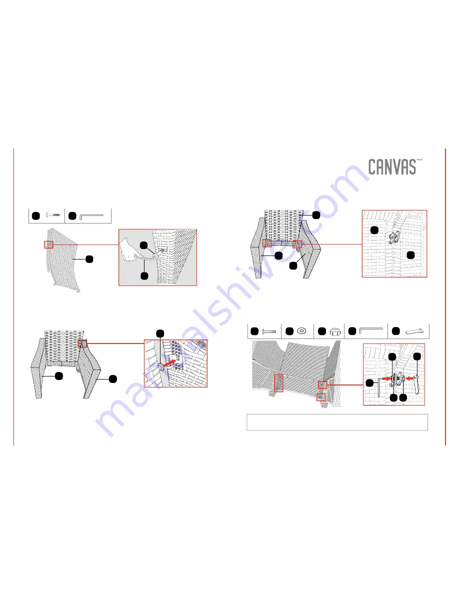
Step 1
Requires
B, G
Insert the shank of the screw (B) into the corresponding hole located on the left
side of the back panel (3). Tighten the screws using the hex key (G). Repeat the
same procedure on the right side of the back panel.
Step 3
Requires
1, 2, 3
Align holes located on the lower portion of the back panel (3) with the
corresponding holes of the right arm frame (2). Repeat the same procedure for
the left arm frame (1).
Step 2
Requires
1, 2
Lock the head of the screws (B) into the respective slots located on the left arm
frame (1) and the right arm frame (2).
G
3
B
2
1
B
G
B
1
3
2
3
2
Step 4
Requires
A, C, E, G, H
Insert the screw (A) with one washer (C) into the aligned hole. Tighten the screw
using another washer and a screw nut (E). Use the hex key (G) to firmly tighten
the screw. Use the wrench (H) to secure the nut from moving. Follow the same
procedure for the second screw. Repeat the same procedure for the left arm
frame.
C
A
E
G
H
G
H
A
E
C
NOTE:
Do not tighten the screws completely until all four screws are installed.


