CDE360 Vector Control AC Drive Chapter 6 Parameters Description
Note:
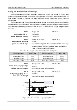
If necessary,please use Y terminals to control external relays in multi-pump configuration.
Do not directly use Y terminals.
E6.01
Range: 1~4
Default: 1
Number of
motors
Motor numbers of multi-pump control system.
E6.02
Range: 0.0~100.0
Default: 0.0
Reference step 1
Unit: %
Add a percentage increment(base on PID setting) to the initial PID setting
value.
Be valid when there is at least 1 auxiliary motor running.
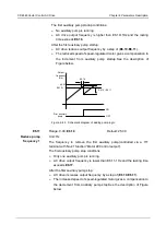
Example: The AC drive controls 3 parallel pumps to supply water through
pipeline.E5.05 sets the pipeline pressure.
When the water consumption is small,there is only frequency pump
running.The auxiliary pumps will be added one by one as the water
consumption increasing.
Reference step is E6.02 when the first auxiliary pump starts.
Reference step is the sum of E6.02 and E6.03 when the second
auxiliary pump starts.
Reference step is the sum of E6.02, E6.03and E6.04 when the third
auxiliary pump starts.
E6.03
Range: 0.0~100.0
Default: 0.0
Reference step 2
Unit: %
See the parameter description of
E6.02
.
Be valid when there is at least 2 auxiliary motor running.
E6.04
Range: 0.0~100.0
Default: 0.0
Reference step 3
Unit: %
See the parameter description of
E6.02
.
Be valid when there is at least 3 auxiliary motor running.
E6.05
Range: 00~11
Default: 00
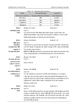
Interlock
functions
Interlock function is used to indicate whether each motor is connected to
multi-pump control logic or not.
Unit's digit: interlock enable
0:disabled 1:enabled
Ten's digit: interlock mode
0:decided by X terminals 1:decided by E6.06


