CDE360 Vector Control AC Drive Chapter 5 Parameter List Table
-
57
-
Function
Code
Name
Range
Default
Step
Description
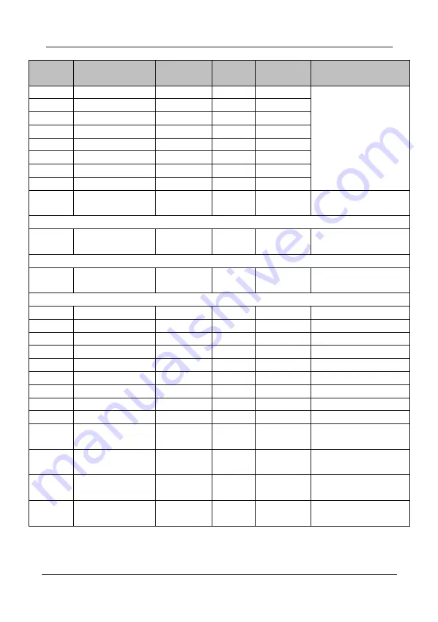
C1.02
Y2 function
0~45
7
1
Same As C1.01
C1.03
Y3 function
0~45
0
1
C1.04
T1 function
0~45
13
1
C1.05
T2 function
0~45
0
1
C1.06
T3 function
0~45
0
1
C1.07
T4 function
0~45
0
1
C1.08
T5 function
0~45
0
1
C1.09
T6 function
0~45
0
1
C1.10
Y terminals active
state logic
000~111
000
1
0: positive logic
1: Negative logic
Unit's digit:
Y1
Ten's digit:
Y2
Hundred's digit:
Y3
C1.11
T1~T4 active state
logic
0000~1111
0000
1
0: positive logic
1: Negative logic
Unit's digit:
T1
Ten's digit:
T2
Hundred's digit:
T3
Thousand's digit:
T4
C1.12
T5~T6 active state
logic
00~11
00
1
0: positive logic
1: Negative logic
Unit's digit:
T5
Ten's digit:
T6
C1.13
Y1 output delay time
0.0~3000.0
0.0
0.1Sec
C1.14
Y2 output delay time
0.0~3000.0
0.0
0.1Sec
C1.15
Y3 output delay time
0.0~3000.0
0.0
0.1Sec
C1.16
T1 output delay time
0.0~3000.0
0.0
0.1Sec
C1.17
T2 output delay time
0.0~3000.0
0.0
0.1Sec
C1.18
T3 output delay time
0.0~3000.0
0.0
0.1Sec
C1.19
T4 output delay time
0.0~3000.0
0.0
0.1Sec
C1.20
T5 output delay time
0.0~3000.0
0.0
0.1Sec
C1.21
T6 output delay time
0.0~3000.0
0.0
0.1Sec
C1.22
Interval of Y1 output
active state
0.0~600.0
0.0
0.1Sec
C1.23
Interval of Y2 output
active state
0.0~600.0
0.0
0.1Sec
C1.24
Interval of T1 output
active state
0.0~600.0
0.0
0.1Sec
C1.25
Interval of T2 output
active state
0.0~600.0
0.0
0.1Sec


