8
3 INSTALLATION
Only skilled personnel should install the machine. All con-
nections must be carried out according to current regula-
tions, and in full observance of safety laws (regulation CEI
26-10 - CENELEC HD 427).
1. Place the welding machine in a stable and safe position.
Air must circulate freely, both incoming and outgoing,
and the welding machine must be protected from entry
by liquids, dirt, metal filings, etc.
2. Make sure that the supply voltage matches the voltage
indicated on the specifications plate of the welding
machine. When mounting a plug, make sure it has an
adequate capacity, and that the yellow/green conductor
of the power supply cable is connected to the earth pin.
The capacity of the overload cutout switch or fuses
installed in series with the power supply must be equiv-
alent to the absorbed current I1 of the machine.
Any extension cords must be sized appropriately for the
absorbed current I1.
If the power supply is 115V, the machine may run for
voltages between 96V and 140V.
If the power supply is 230V, the machine may run for
voltages between 190V and 260V.
The machine must be switched off when changing the
power supply.
3. Pacemaker wearers are prohibited from using the
machine or approach the cables.
4. Fully insert the earth cable plug into the + socket and
turn clockwise.
5. Fully insert the gun plug into the - socket and turn clock-
wise.
6. Turn on the welding machine using the I switch. (start-up
and shutdown should not be repeated frequently,
because dissipating the energy contained in the capac-
itors may cause overheating and damage).
7. To limit exposure to the magnetic field, keep the gun
cable on the side of the hand holding it, avoiding wrap-
ping the cable around.
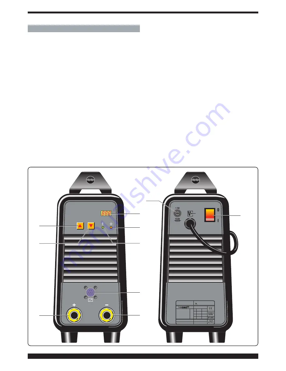
3.1
DESCRIPTION OF THE EQUIPMENT
A-
Key to increase the capacitor charge voltage
B-
Key to reduce the capacitor charge voltage
C-
LED indicating that the machine is on
D-
LED that lights during welding
E-
Displaying showing the capacitor charge voltage
F-
Positive output terminal
G-
Negative output terminal
H-
Torch trigger connector
I-
Main switch
J-
Fuse Ø 6.3x32 (delayed type). The equipment is fitted
with a 16A fuse for 115V power supply; a 10A fuse may
be used for 230V power supply.
A
B
F
G
H
C
D
E
J
I
Fig. 1


