background image

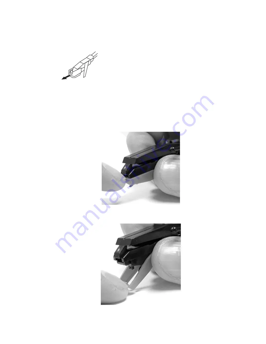
2.  Remove the white protective Stylus Cover (if necessary). 


3.  Hold the bottom of the CARTRIDGE

  (14)

 with your thumb & index finger 

as shown below in Fig. 3a.  With your other thumb carefully push down on 
the  top  edge  of  the  the  Red  Stylus  Assembly  (Red  piece  includes  the 
needle)  until  the  Stylus  Assembly  separates  from  the  CARTRIDGE

  (14)


as shown in Fig 3b. 


FIG 3a 


             FIG 3b 

Summary of Contents for CH196B/R

Page 1: ...MODEL CH196B R 3 Speed Stereo Turntable With Built in Speakers ...

Page 2: ...nce to radio or television reception which can be determined by turning the equipment off and on the user is encouraged to try to correct the interference by one or more of the following measures Reorient or relocate the receiving antenna Increase the separation between the equipment and receiver Connect the equipment into an outlet on a circuit different from that to which the receiver is connect...

Page 3: ...NEARM LOCK 4 TONEARM REST 5 TONEARM LEVER 6 AUTO STOP CONTROL SWITCH 7 SPEED CONTROL SWITCH 8 POWER VOLUME KNOB 9 POWER INDICATOR LIGHT 10 45 RPM ADAPTER 11 3 5mm HEADPHONE JACK 12 AUDIO OUTPUTS Standard RCA Red White 13 AC 120V 50Hz to DC 5V INPUT 14 CARTRIDGE 15 STYLUS NEEDLE 4 3 14 15 ...

Page 4: ...ite protective stylus cover as it can protect the stylus when the turntable is not in use or is being moved POWER 1 Plug the supplied AC 120V to DC 5V power adapter into the AC 120V 50Hz to DC 5V INPUT 13 located on the rear of the turntable 2 Insert the wall plug of the power adapter into an electrical wall outlet 3 Turn the Turntable ON by turning the POWER VOLUME KNOB 8 clockwise NOTE You will ...

Page 5: ...ARM 2 in place using the TONEARM LOCK 3 when the player is not in use or the turntable is being moved Failure to do so can cause damage to the cartridge or stylus 4 Turn the POWER VOLUME KNOB 8 clockwise to turn the Player ON 5 Adjust the Volume to the desired level by turning the POWER VOLUME KNOB 8 6 Raise the TONEARM 2 by slowly lifting the TONEARM LEVER 5 7 Using your finger move the TONEARM 2...

Page 6: ... Simply plug the Red White ends of the RCA Cable into the corresponding Red White AUDIO OUTPUT JACKS 12 on the rear of the player Then connect the other Red White ends of the RCA Cable into the corresponding Red White Audio Input Jacks on your External Speakers or Stereo system LISTENING TO THE TURNTABLE WITH HEADPHONES To use Headphones with this player connect any headphone with a 3 5mm jack int...

Page 7: ...he CARTRIDGE 14 with your thumb index finger as shown below in Fig 3a With your other thumb carefully push down on the top edge of the the Red Stylus Assembly Red piece includes the needle until the Stylus Assembly separates from the CARTRIDGE 14 as shown in Fig 3b FIG 3a FIG 3b ...

Page 8: ... FIG 4a INSTALLING THE NEW STYLUS NEEDLE NOTE DO NOT DIRECTLY TOUCH THE STYLUS NEEDLE 15 DURING INSTALLATION OR YOU MAY CAUSE PERMANENT DAMAGE TO THE STYLUS 15 1 Hold the front tip of the Stylus Assembly with your thumb and index finger and insert the rear edge of the Stylus Assembly on the CARTRIDGE 14 as shown in Fig 5a FIG 5a ...

Page 9: ...A CORRECTLY POSITIONED STYLUS Under normal use a STYLUS 15 should last for about 50 60 hours of record play It is recommended the STYLUS 15 be replaced as soon as you notice a deterioration of the sound quality Use of a worn out STYLUS 15 may damage records Playing 78 RPM records will cause the STYLUS 15 to wear out much faster than 33 or 45 RPM records A replacement STYLUS 15 can be purchased by ...

Page 10: ...htly touching the tip of the diamond needle If a replacement STYLUS 15 is needed please contact our Customer Support Center at 1 855 998 4278 to purchase a replacement NO SOUND Make sure the white protective Stylus Cover has been removed from the cartridge Increase the volume by turning the POWER VOLUME KNOB 8 clockwise as it may be set too low Confirm there is nothing plugged into the 3 5mm HEADP...

Page 11: ...or troubleshooting To contact us please call 1 855 998 4278 This warranty applies only under conditions of normal use Our products are not intended for outdoor use There are no consumer serviceable electronic parts contained in this product and any attempt by the owner to service or repair the unit will immediately void all warranty coverage The purchaser of this product does have the ability to r...

Page 12: ...Schoenfeld International Inc and CAPEHART 5001 American Boulevard West Suite 275 Bloomington Minnesota 55437 Schoenfeld International Inc 2014 CH196B R Ver 1 0 February 2014 ...

Reviews: