background image

 31 

Rig Lines for Remote Course Setting 


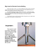
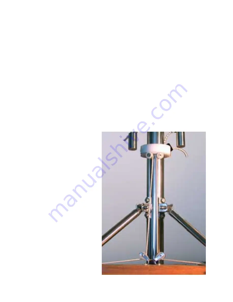
Friction of a 5/32 or 3/16 in. (4 - 5 mm) endless line inside a groove at the base 

of the control disk rotates the revolving turret at the top of the windvane tower and 
allows to set a precise course from a remote position. 


Two rollers guide this line down to blocks at deck level.  Leading this endless 

line through blocks 

around the cockpit 

(along the coaming) allows to 

set

 the 

course


from any position

 in the cockpit, even from below by reaching through the 

companionway. 


If the turret becomes too stiff and the line slips in the groove, put a rubber band 

in the bottom of the groove to increase friction. 


Important :  


The turret is built 

to revolve reasonably 
freely at the top of the 
tower, so if this 
endless line is not 
used, r

ig at least a 

line to the pushpit or 
backstay, that 
creates additional 
friction

 and maintains 

the course 

Summary of Contents for Self-Steering

Page 1: ...Cape Horn Owner s Manual Self Steering ...

Page 2: ...2 ...

Page 3: ...elf Steering Owner s Manual For operation and installation of Integrated and outboard models CapeHorn Marine Products Inc 26 Guy Racicot St Oka QC Canada J0N 1E0 Tel 450 479 6314 www capehorn com mail capehorn com ...

Page 4: ... 10 Ideal size of the servo pendulum 10 BALANCE UNDER SAIL 10 Reef when needed 11 CONNECTION TO ELECTRIC AUTOPILOT 12 STOWAGE 12 MAINTENANCE 12 B INSTALLATION 13 INTEGRATED MODELS 13 1 A POSITION THE GEAR 14 Height Above Water 14 Positioning the gear fore and aft 14 Provision for 360 Quadrant Movement 15 Provision for connecting an autopilot to the steering oar 15 1 B TRACE THE CENTRE OF THE MOUNT...

Page 5: ...Connection to Yacht s Steering System 24 Position of the Turning Blocks 25 Examples of direct connections 26 Jamming cleats 28 CONNECTION TO WHEEL OR TILLER 29 Connection to Wheel 29 Connection to Tiller 30 RIG LINES FOR REMOTE COURSE SETTING 31 OUTBOARD MODELS 32 INSTALLATION OF THE VARUNA OR JOSHUA 32 Assembling the Varuna or Joshua 32 Installation to the transom 33 Control Lines 33 Connecting a...

Page 6: ... of the vane turns the stock of the steering oar Because of the forward movement of the boat through the water this turn of the steering oar also called Servo pendulum causes it to be pushed with great force sideways turning the horizontal shaft that passes through the transom rotating the quadrant at its the steering oar comes back to vertical The steering oar servo pendulum can also be controlle...

Page 7: ... course it is difficult for beginners to know which way the turret should be turned This is easily determined when one asks the question Do I want the boat to head up into the wind or bear off If you want to head up into the wind the windward side of the vane should be turned towards the bow Conversely if you want to bear off the vane should be turned towards the stern b Limit Yaw When we have lea...

Page 8: ...nt MPORTANT If the boat needs weather or lee helm on a given point of sail be sure to invert the trim of the control lines after you have tacked Any lack of sail balance that the rudder angle was correcting on the previous tack is now increased by this rudder angle being inverted Failure to invert the trim on a new tack makes the job much more difficult for any self steerer After the gear is conne...

Page 9: ...ower the more the counterweights have to be offset to the side to balance the added weight Do not re adjust counterweights to limit yaw Use the bungee cord that limits the tilt of the crescent instead Steering Oar The steering oar is linked to its stock with three turns of shock or bungee cord between the mounting plate of the oar and the hook on the stock maintaining the two notches on the plate ...

Page 10: ... between 8 and 12 of the yacht s rudder area Closer to 8 for a high aspect ratio partially balanced rudder steering a well balanced boat and closer to 12 or more for a low aspect ratio rudder on a boat that is not so well balanced or has a wheel steering system with a lot of internal friction We normally take the yacht s rudder dimensions and the height of the horizontal axis above the waterline i...

Page 11: ...d if necessary This improves sail balance and the boat sails a much truer course Reef when needed As the wind builds up a yacht acquires weather helm This is normal and desirable up to a point In fact increasing weather helm is the first symptom of an over canvassed boat Often the wind freshens gradually and as there is no one at the tiller or wheel this added weather helm goes unnoticed Whether i...

Page 12: ...he length of the rod It is possible to mount the autopilot elsewhere and link it to the steering mechanism with light control lines Note rigging steering lines to the control rod also renders remote power steering possible Stowage For short periods the steering oar can be swung 180 to rest along the windvane tower For longer periods the steering oar and windvane with crescent are easily removed an...

Page 13: ...e while the yacht is afloat It is rendered much easier if the yacht s stern is brought to a stable dock with the yacht made fast to it so it will move as little as possible Installation of Integrated Models Installation of the models Jean du Sud and Spray is done in 5 steps 1 a Position the Gear b Trace the centre of the Mounting Tube hole 2 Drill the hole and fasten the Mounting Tube 3 Insert the...

Page 14: ...void cutting or moving the backstay chainplate gusset Performance of the gear will not be affected if it is offset to one side provided it is kept parallel to the keel It can even be offset enough to allow a transom mounted rudder to pivot Height Above Water Drag of the servo pendulum is kept to a minimum when the metal plate that links the servo pendulum to its stock is kept out of the water Ther...

Page 15: ... 32 mm for Spray If space inside the lazarette or in the cockpit is limited to one half circle below or above the horizontal axis the gear will work just as well but the possibility of swinging the pendulum up for storage alongside the windvane tower will be lost The quadrant is delivered with a plastic disk in its center at the place where the horizontal axle will be a 1 4 hole in its center make...

Page 16: ...ost probably is Carefully mark the centre of the hole on the transom or hull both inside and out When this is done do not grab the drill yet Repeat each step of the whole measuring operation to double check Remember this is the most critical part of the installation process and has to be done with greatest care If you arrive at the same results twice you can go ahead with a clear conscience and dr...

Page 17: ...e are slightly different the aft one is larger due to the fact that at welding the horizontal axle may have become slightly oval and the chamfer is a bit deeper due also to the weld Hence the tube must be inserted accordingly Fasten the Forward End The forward end of the mounting tube is held in place with two struts provided standard length 18 in 45 cm for Jean du Sud and 24 in 60 cm for Spray Th...

Page 18: ...The surface of the hull is ground to expose bare fibreglass all surfaces are coated with epoxy then bedded in thickened epoxy the bevelled edges of the pad are covered with glassfibre tape The length of the struts is fine tuned using the turnbuckle end to ensure the tube is parallel to both the waterline and plane of the keel If both struts and turning block are mounted on a pad it is a good idea ...

Page 19: ... the West System filler no 404 is best you will need less but 403 and 406 will provide adequate mechanical strength 405 is for wood Uncured epoxy can be cleaned with alcohol methylated spirits which is less aggressive than acetone A light bead of sealant will make a nice finish outside Metal Hulls The Mounting Tube can be welded to a steel hull provided welding is done carefully to minimize tube d...

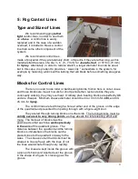
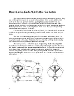
Page 20: ... is mounted one way or the other is determined by the most convenient placing of the first pair of turning blocks and the most direct routing of the control lines to the rudder quadrant wheel or tiller When the control lines are pulling the tiller or rudder quadrant from a position forward of the rudder stock the lines are connected directly when the windvane quadrant is above and they have to be ...

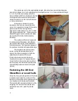
Page 21: ...he moving ring to which it is bolted may bind and keep the axis from turning freely If in spite of your precaution the ring binds after it has been connected to the base of the tower it can be brought back in line by enlarging the four holes on one side to allow the tower to pivot until it is brought back in line Since the U shaped bracket covers the holes nothing will show Bringing the threaded b...

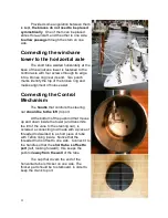
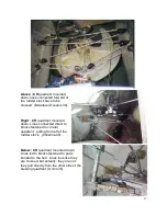
Page 22: ...nt of holes easier Connecting the Control Mechanism The handle that controls the steering oar should be to the left to port At the bottom of the pushrod that moves up and down inside the tower and transmits the tilt of the vane to the steering oar is screwed a connecting rod made with a piece of threaded rod welded to a short piece of tube with Teflon lining inside Notice that the threaded rod is ...

Page 23: ...r short periods then rest and since they are continually working they may overheat Ordinary plain bearing blocks are perfectly OK and are cheaper Minimum sheave diameter should be 34 or 40 mm for JdS and 40 45 mm for Spray The control lines are fed through a hole at either end of the groove on the edge of the quadrant and prevented from pulling through with a figure eight knot They are led through...

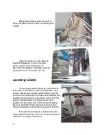
Page 24: ...event fouling the steering cables with the control lines when they are loose The vane is connected by putting the lines in tension and cleating them it is adjusted for weather or lee helm if any is needed to maintain a given point of sail by varying the length of the lines Releasing the lines from the jamming cleats instantly disconnects the vane and allows to take over manually Whenever possible ...

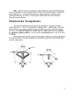
Page 25: ...eal ratio between the tilt angle of the pendulum quadrant and the rudder angle is 2 1 for 10 of pendulum quadrant tilt 5 rudder angle Since the turning block on the rudder quadrant or tiller divides the travel by half and doubles the force the distance between this block and the rudder axis should be equal to the windvane quadrant radius 8 in 20 cm for Jean du Sud and 10 1 2 in 27 mm for Spray Mos...

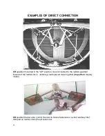
Page 26: ... position lines connected to the rudder quadrant forward of the rudder stock Jamming cleats placed close together Cape Horn display model CH quadrant below axle control lines led to blocks fastened on a short auxiliary tiller clamped on rudder stock Pan Oceanic 43 ...

Page 27: ...ted down Lines connected direct to blocks fastened to circular quadrant pulling from aft of the rudder stock Christina 40 Below CH quadrant mounted down Lines led to blocks fastened to pads bonded to the hull Lines look like they are crossed but actually they are not they pull directly from the other side of the steering quadrant Union 36 ...

Page 28: ...in easy reach of the wheel Whenever possible they should placed side by side which allows tying the two lines in a knot when the rudder is amidships and quadrant and pendulum are vertical and to find this position automatically by pulling the two lines together If the cleats can not be located together the lines should be marked to locate the position rudder amidships and pendulum quadrant vertica...

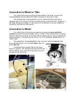
Page 29: ...ction to Wheel The control lines turn the steering wheel by going around grooved Delrin cylinders placed on the wheel spokes then to a cleat These cylinders can be placed closer or farther from the hub so the ideal ratio of rudder angle for a given quadrant tilt can be arrived at This ideal ratio is 2 to one for 10 of pendulum quadrant tilt 5 of rudder angle I f the quadrant is mounted above the a...

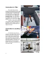
Page 30: ...Tying the control lines together at the position rudder amidships and pendulum vertical makes it easier to tighten the lines and cleati them in a single movement Connection to auxiliary tiller If control lines are led to an auxiliary or emergency tiller this tiller can be kept shorter by leading the lines through blocks fastened to the tiller at a distance from the rudder axis equal to the quadran...

Page 31: ...ndless line through blocks around the cockpit along the coaming allows to set the course from any position in the cockpit even from below by reaching through the companionway If the turret becomes too stiff and the line slips in the groove put a rubber band in the bottom of the groove to increase friction Important The turret is built to revolve reasonably freely at the top of the tower so if this...
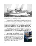
Page 32: ...ace the frame on the base of the tower and fasten the 3 remaining holes one on top and 2 each side using the 3 remaining bolts that are longer than the first one since the frame adds some thickness Do not tighten one bolt before all 3 are engaged Allowing a tiny motion will help Do not tighten these bolts too hard before the last step is done 3 Engage the first of the last 2 bolts these bolts are ...

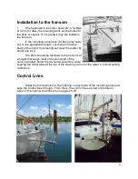
Page 33: ...he steering oar clear the rudder by about one inch The arms should be fastened to the transom at a height that keeps most of the wood part of the servo pendulum below the dynamic waterline while keeping the metal plate at the top of the steering oar out of the water in normal sailing conditions Control Lines Shackle a turning block to the half ring on each side of the mounting arms and pass the co...

Page 34: ...pilot rod pulls the bungee line stretches When the autopilot pushes the bungee pulls the arm in the other direction When the autopilot is not used simply disconnect by removing the vertical arm from its receptacle It can be left hanging or tied to one side until the autopilot is used again Don t forget to remove the vane when using the autopilot Extended Varuna or Joshua on step stern If the step ...

Page 35: ...nal struts to either the boomkin or the hull If there is enough room the windvane tower can be located inside the V of the boomkin An Omega shaped strap can be used to fasten the tower to the boomkin Additional diagonal struts can be added to the boomkin for more support Control lines are led to tiller as described on pages 26 32 ...

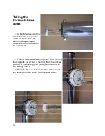
Page 36: ...lot wedge shaped connection to the co axial in control rod 2 Pull the two screws fastening the 1 in bushing that supports the aft end of the rod Mark the precise position of the bushing see below Pull the rod with the bushing from af 3 Remove the in fore and aft bolt at the top of the servo pendulum stock Pull the stock down ...

Page 37: ...hould be abt 1 mm of play fore and aft Lateral The hole guiding the control rod in the 1 in bushing is offset 0 020 to correct any mis alignment between the axis of the horizontal and vertical tubes If after re assembling you find a hard spot when rotating the crank in the left semi circle rotate this bushing to move the control rod laterally until it moves freely and there is no hard spot and rep...

Page 38: ...embling make sure the turret is pushed down all the way as the precise length of the connecting rod in relation to the total length of the tower is critical to maintain the servo pendulum in the vertical position when the vane is also vertical If it is not and the crank at the aft end of the horizontal axle is not bent out of shape the length of the connecting rod is re adjusted by loosening the l...

Page 39: ...asier to operate Those photos could also inform the owner of a similar boat who wants it steered by a CapeHorn mail capehorn com Guarantee We build the Cape Horn with the greatest of care and when we ship a unit we have the assurance that it could steer us around the world We naturally expect that comparable care will be given to installation We guarantee its performance for one circumnavigation 2...

Page 40: ...40 ...

Reviews: