background image

Curvation & Siesta Series Manual - V2.2

© Capital Fireplaces 2017

3

1. General Notes

Th

is Capital Fireplaces gas appliance is a High Efficiency, Balanced Flue Live Fuel Effect appliance. 

It provides radiant and convected heat using the latest burner technology. As well as having a variable 

heat output, these fires also utilise a special control system that allows the appliance to use double 

burners* for high output or a single burner for lower outputs.

When fitted with double burner system, the front burners is designated as the “Main” Burner, the second 

burner will be designated as the “Effect or Auxiliary” Burners. The Effect burner can be switched ON or 

Off whilst the appliance is alight.

Before Installation, check that the local distribution conditions, nature of the gas and pressure, and 

adjustment of the appliance are compatible.

This appliance is intended for use on a gas installation with a governed meter.

This Gas Installation may only be installed by a registered professional competent person (Gas Safe 

installer in the UK).  The installation must adhere to the requirements of the local and national Building 

regulations and national standards. The installation manual must also be followed.

Ensure that the Flue Terminal is not in any way obstructed and is clear of vegetation, i.e. trees, shrubs 

etc. and that no objects are leant against the terminal or guard.

Always clean the Window Panel before the fire is ignited. Any finger prints must be removed, as these 

will be burnt into the glass and will be un-removable.

Do not operate this appliance if the glass panel has been broken (or cracked), removed or with firebox 

access panels open.

Only flue approved by Capital Fireplaces for this appliance may be used.

This  appliance  is  a  balanced  flue  product  and  is  room  sealed  and  as  such  requires  no  additional 

ventilation  for  operation.  However  an  adequate  supply  of  fresh  air  to  maintain  temperatures  and  a 

comfortable environment is recommended.

This appliance is designed as a heating appliance, and as such will get very hot in operation; all surfaces 

(except the controls and access door) are considered to be working surfaces and as such should not 

be touched. The front windows and surrounds are not considered to be fully secure guards against 

accidental contact. It is recommended that an approved fire screen be used if children, the elderly or 

persons with limited mobility are to be present in the same area.

Do not place curtains, laundry, furniture etc. within a safe distance of 300mm of this appliance.

Do not attempt to burn rubbish on this appliance.

If this appliance is extinguished, on purpose or other, no attempt to relight should be made within 3 

minutes.

*Not available on Single Burner models

Summary of Contents for Curvation:Siesta

Page 1: ...her counties see technical data However to install appliance in other countries modification of the appliance and its method of installation may be necessary in order to use the appliance safely and correctly The manual for the local language must be obtained Contact Capital Fireplaces for further information www capitalfireplaces co uk ...

Page 2: ...hat there are no flammable materials closer than the recommended distance specified NOTE Ensure you report the installation of your stove to your local authority The owner of the property is personally responsible for ensuring compliance with all mandatory safety requirements and that the installation is carried out by an approved and qualified installer Contents 1 General Notes 3 2 User Instructi...

Page 3: ...ted and is clear of vegetation i e trees shrubs etc and that no objects are leant against the terminal or guard Always clean the Window Panel before the fire is ignited Any finger prints must be removed as these will be burnt into the glass and will be un removable Do not operate this appliance if the glass panel has been broken or cracked removed or with firebox access panels open Only flue appro...

Page 4: ...out of the area at this time 2 3 Control Overview 2 3 1 Basic Manual Control 1 Igniting the Pilot Light a From the OFF position depress the control knob for five seconds only pilot gas flows b Turn the control knob anti clockwise through the PILOT position and continue turning until the igniter clicks if the Pilot flame lights hold for ten seconds only pilot gas flows If the Pilot has not Ignited ...

Page 5: ... control clockwise through the LOW setting to the PILOT setting The appliance can be left in this position however we would recommend turning the appliance OFF if not required within a few hours 5 Turning the appliance OFF From any heat setting or PILOT Depress and turn the Control knob fully clockwise to reach the OFF position and release the control knob The appliance will now be OFF ...

Page 6: ...trol IMPORTANT We only recommend Duracell Ultra Power alkaline batteries Rechargeable batteries are not to be used Under normal conditions batteries should last approximately 12 months x4 AA Batteries required in the controller unit x2 AAA Batteries required in the remote control ...

Page 7: ...Curvation Siesta Series Manual V2 2 Capital Fireplaces 2017 7 ...

Page 8: ...Curvation Siesta Series Manual V2 2 Capital Fireplaces 2017 8 ...

Page 9: ...Curvation Siesta Series Manual V2 2 Capital Fireplaces 2017 9 ...

Page 10: ...Curvation Siesta Series Manual V2 2 Capital Fireplaces 2017 10 ...

Page 11: ...ppliance 2 5 Cleaning and Maintenance This appliance should be inspected and serviced once a year by a qualified competent and registered person The inspection and maintenance must at least ensure that the appliance is working correctly and safely It is advisable to clean the appliance of any dust and debris before regularly during the heating season and especially if the appliance has not been us...

Page 12: ...se 3 3 Appliance Installation Determine the position required for the appliance Create a gas connection for the appliance in approximately the correct location for the gas controls The gas controls are connected to the Burner of the appliance Do not make any adjustments to the appliance The Flue system should be fitted with a minimum clearance of 25mm from any combustible objects or materials this...

Page 13: ... or Building Extension Where a flue terminal is sited within a carport or building extension it should have at least two completely open and unobstructed sides The distance between the lowest part of the roof and the top of the terminal should be at least 600mm Note A covered passageway should not be treated as a carport Flues should not be sited in a covered passageway between properties 3 4 4 Ba...

Page 14: ...rain pipe or soil pipe 300 H From an internal or external corner 600 I Above ground roof or balcony level 300 J From a surface facing the terminal 600 K From a terminal facing the terminal 600 L From an opening in the car port e g door window into the dwelling 1200 M Vertically from a terminal on the same wall 1500 N Horizontally from a terminal on the same wall 300 P From a vertical structure on ...

Page 15: ... Flue Run H m for Ø100 150 flue 0 5 0 5 1 1 1 5 1 5 2 2 2 5 2 5 3 3 3 5 3 5 4 4 4 5 4 5 5 5 5 5 5 5 6 6 6 5 6 5 7 7 7 5 and over 7 5 Minimum Vertical Flue Height 0 5m 3 4 7 Vertical Roof Vent Termination C31 Flue sizing Ø100 150 Connector on Appliance for Metaloterm US concentric flue system Ø100 150 Adaptor for Poujoulat PGI or Muelink Grol concentric flue systems Ø100 150 Maybe used Through out ...

Page 16: ...hield When commissioning or servicing the Appliance Cross Lighting must be checked to ensure smooth lighting of the main burner from the Pilot Flame and smooth lighting of the effect burners from the main Burner Fuel arrangements shown below are for the Double burner featuring the 2nd Thermocouple Ensure that when fitting the fuel beds the 2nd thermocouple remains clear of the Fuel Bed media as sh...

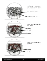
Page 17: ... the bags of Embers over the top of the burners as shown keeping the pilot area clear Pilot and Cross Light left clear 2nd Thermocouple left clear Position Logs S1 S2 S3 as shown in the diagram Log S1 Log S2 Log S3 Position Logs S4 S5 as shown in the diagram Log S5 Log S4 ...

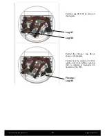
Page 18: ... 18 Position Logs S6 S7 as shown in the diagram Log S7 Log S6 Position the Fircone Log S8 as shown in the diagram Finally check the appliance for Pilot ignition and cross lighting ensuring that no material is impinging the operation of the Pilot Fircone Log S8 ...

Page 19: ...t pressure and burner pressure 1 Turn off the gas valve on the appliance 2 Release the screw on the Inlet Pressure test point on the gas valve and connect a manometer 3 Check that the measured pressure is as the prescribed supply pressure 4 Perform the test when the appliance is burning on full inc effect burners and with only the pilot alight 5 If the pressure is low check the gas supply pipes ar...

Page 20: ...the safe operation of the appliance 4 1 Cleaning the Ceramics Remove the ceramics as detailed in A E above Gently clean the ceramics in the open air using a soft brush and a vacuum cleaner Where necessary replace damaged components only with genuine Capital Fireplaces specified parts Seal any scrap ceramics in plastic bags and dispose at proper refuse sites When using a vacuum cleaner it is recomm...

Page 21: ...Electrode Lead 1008 Thermocouple 1009 Injector Natural Front 1010 Injector Natural Rear 1011 Injector LPG Front 1012 Injector LPG Rear 1013 Complete Burner Assembly Natural 1014 Complete Burner Assembly LPG 1015 Burner Seal 1016 Grate Assembly Standard 1017 Grate Assembly Tear Deform 1018 Gas Valve Assembly Natural 1019 Gas Valve Assembly LPG 1020 Latching Solenoid 1021 Receiver unit 1022 Handset ...

Page 22: ...t 37 mbar GR Greece I2H G20 at 20 mbar I3 G31 G31 at 28 37 mbar I3P 37 G31 at 37 mbar HU Hungary NOT APPROVED NOT APPROVED HR Croatia I2H G20 at 20 mbar I3P 37 G31 at 37 mbar IE Ireland I2H G20 at 20 mbar I3 G31 G31 at 28 37 mbar I3P 37 G31 at 37 mbar IS Iceland NOT APPROVED NOT APPROVED IT Italy I2H G20 at 20 mbar I3 G31 G31 at 28 37 mbar I3P 37 G31 at 37 mbar LT Lithuania I2H G20 at 20 mbar I3 G...

Page 23: ... m hr 0 796 0 796 0 850 0 796 0 761 0 850 Burner Pressure hot mbar 15 5 15 5 22 3 15 5 18 7 22 3 Injector Marking 320 Front 280 Rear Pilot 446 1385 44 Efficiency Class 2 Nox Class 5 LPG Double Burner Gas Type G30 31 G31 I3B P 30 50 I3 I3P 37 50 I3P 30 Supply Pressure mbar 30 50 28 30 37 37 50 30 Nominal Heat Input Gross Hs kW 5 9 5 9 5 9 5 1 Nominal Heat Input Nett Hi kW 5 4 5 4 5 4 4 7 Consumptio...

Page 24: ... 0 673 0 644 0 723 Burner Pressure hot mbar 19 7 19 7 24 5 19 7 24 5 Injector Marking 480 Pilot 446 1385 44 Efficiency Class 2 Nox Class 5 LPG Single Burner Gas Type G30 31 G31 I3B P 30 50 I3 I3P 37 50 I3P 30 Supply Pressure mbar 30 50 28 30 37 37 50 30 Nominal Heat Input Gross Hs kW 4 1 4 1 4 1 3 6 Nominal Heat Input Nett Hi kW 3 8 3 8 3 8 3 3 Consumption m hr 0 116 0 116 0 144 0 131 Burner Press...

Page 25: ...Curvation Siesta Series Manual V2 2 Capital Fireplaces 2017 25 5 3 Dimensions Curvation models with side windows Curvation Tall Curvation Pedestal Curvation Midi ...

Page 26: ...Curvation Siesta Series Manual V2 2 Capital Fireplaces 2017 26 Siesta Tall Siesta model with side windows ...

Page 27: ...Curvation Siesta Series Manual V2 2 Capital Fireplaces 2017 27 Appendix 1 Mertik Fault Finding Chart ...

Page 28: ...Curvation Siesta Series Manual V2 2 Capital Fireplaces 2017 28 ...

Page 29: ...Curvation Siesta Series Manual V2 2 Capital Fireplaces 2017 29 ...

Page 30: ...Farm Industrial Estate Village Farm Road Pyle Bridgend CF33 6BL w www capitalfireplaces co uk What comes with your stove Manual Ceramic Log Set Ember Set Remote Control Fire Grate Retainer Bars CE Plate Balanced Flue Collar ...

Reviews: