Refit the grease filters, the carbon filters
(fig.17) and close the glass panel.
7
Built-in installation
In case of built-in version remove the
stainless steel cover (fig. 11)
Ducted Version
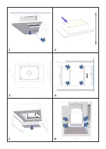
Mark the holes to fix the product into the false
ceiling (Fig.3).
Make the holes marked, by a drill bit diameter 8mm,
and place the metric plugs provided in the holes. In
the built-in version it is possible to select the air
outlet side.
The product has been assembled with the air
outlet of the motor placed on the short side but
it is possible to select the side of the cooker hood
where the air extracted can be discharged, as
follows:
open the glass panels, following the instructions
mentioned in the opening the glass panels section
and remove the grease filters and carbon filters.
Unscrew the four screws shown in picture 4.
Remove the lower stainless steel as shown in picture
5.
Now remove the four screws that fix the motor,
shown in picture 6.
Open the hole in the middle of the upper side hood
(fig. 7) or in the long side (fig. 12). Fix the plug to
the hole where there was the motor before, by
means of the four screws supplied. (fig. 9)
Install the motor in the upper side or in the long
side using the four screws earlier removed (fig. 10).
Fix the long screws into the metric plug, install the
hood on the ceiling as shown in picture 13.
Ducting is
not
supplied with the product, this is
to be supplied by the installer depending on the
installation requirements.
If you have selected the output air from the shor
t
side of the hood, it is possible to facilitate the
attachment of the tube by removing the cove
r
shown in Fig. 16.
The use of carbon filters is not necessary in
this case
The false ceiling (plasterboard) must remain above
the wider part of the hood fig. 13. Make
a
structure able to support the weight of the fals
e
ceiling (plasterboard), which must not burden the
hood
.
Recirculating version
After the installation of the hood as described in th
e
previous chapter,
connect a pipe from the motor to the outer part
of the niche
.
Make the electrical connection into the meta
l
box. Refit the grease filters, the carbon filters an
d
close the glass panel
.
7
Built-in installation
In case of built-in version remove the
stainless steel cover (fig. 11)
Ducted Version
Mark the holes to fix the product into the false
ceiling (Fig.3).
Make the holes marked, by a drill bit diameter 8mm,
and place the metric plugs provided in the holes. In
the built-in version it is possible to select the air
outlet side.
The product has been assembled with the air
outlet of the motor placed on the short side but
it is possible to select the side of the cooker hood
where the air extracted can be discharged, as
follows:
open the glass panels, following the instructions
mentioned in the opening the glass panels section
and remove the grease filters and carbon filters.
Unscrew the four screws shown in picture 4.
Remove the lower stainless steel as shown in picture
5.
N
ow remove the four screws that fix the motor,
shown in picture 6.
Open the hole in the middle of the upper side hood
(fig. 7) or in the long side (fig. 12). Fix the plug to
the hole where there was the motor before, by
means of the four screws supplied. (fig. 9)
Install the motor in the upper side or in the long
side using the four screws earlier removed (fig. 10).
Fix the long screws into the metric plug, install the
hood on the ceiling as shown in picture 13.
Ducting is
not
supplied with the product, this is
to be supplied by the installer depending on the
installation requirements.
If you have selected the output air from the short
side of the hood, it is possible to facilitate the
attachment of the tube by removing the cover
shown in Fig. 16.
The use of carbon filters is not necessary in
this case
The false ceiling (plasterboard) must remain above
the wider part of the hood fig. 13. Make a
structure able to support the weight of the false
ceiling (plasterboard), which must not burden the
hood.
Recirculating version
After the installation of the hood as described in the
previous chapter,
connect a pipe from the motor to the outer part
of the niche.
Make the electrical connection into the metal
box. Refit the grease filters, the carbon filters and
close the glass panel.
Make the electrical connection into the metal
box.
The power supply me.tal box is positioned
close to the electrical components and you
can see them after removing the grease fil- ters.
Please connect the cables as you can see in
picture 18.
Ducting is not supplied with the product, this
is to be supplied by the installer depending on
the installation requirements.
If you have selected the output air from the
short side of the hood, it is possible to facilita-
te the attachment of the tube by removing the
cover shown in Fig. 16.
The use of carbon filters is not necessary
in this case
The false ceiling (plasterboard) must remain
above the wider part of the hood fig. 13. Make
a structure able to support the weight of the
false ceiling (plasterboard), which must not
burden the hood.
Recirculating version
After the installation of the hood as described
in the previous chapter,connect a pipe from
the motor to the outer part of the niche.Make
the electrical connection into the metal box.
Refit the grease filters, the carbon filters and
close the glass panel.
Installation of the air outlet with a joint
diameter of 200mm
((NOTE this item is supplied with DDMEXT25
and DDMEXT40 motors only)
In case of a installation with the air outlet diameter
of 200mm, which is possible on the upper side of
this ceiling hood only, please follow these
instructions.
Make the opening for the air outlet diameter of
200mm on the upper side of the product (this
opening is already marked on the body of the unit).
Install the joint with a diameter of 200mm supplied
with the external motor and fix it with the 8 screws
supplied.
The 200mm diameter joint is moved slightly from
the longitudinal axis of the product by 25mm.
Connect the internal motor or the external mo-
tor’s cable to the terminal board found inside
the plastic box of the wiring . Make sure to
respect the colors of cables when performing
the electrical connection (fig.21)
7
Built-in installation
In case of built-in version remove the
stainless steel cover (fig. 11)
Ducted Version
Mark the holes to fix the product into the false
ceiling (Fig.3).
Make the holes marked, by a drill bit diameter 8mm,
and place the metric plugs provided in the holes. In
the built-in version it is possible to select the air
outlet side.
The product has been assembled with the air
outlet of the motor placed on the short side but
it is possible to select the side of the cooker hood
where the air extracted can be discharged, as
follows:
open the glass panels, following the instructions
mentioned in the opening the glass panels section
and remove the grease filters and carbon filters.
Unscrew the four screws shown in picture 4.
Remove the lower stainless steel as shown in picture
5.
Now remove the four screws that fix the motor,
shown in picture 6.
Open the hole in the middle of the upper side hood
(fig. 7) or in the long side (fig. 12). Fix the plug to
the hole where there was the motor before, by
means of the four screws supplied. (fig. 9)
Install the motor in the upper side or in the long
side using the four screws earlier removed (fig. 10).
Fix the long screws into the metric plug, install the
hood on the ceiling as shown in picture 13.
Ducting is
not
supplied with the product, this is
to be supplied by the installer depending on the
installation requirements.
If you have selected the output air from the shor
t
side of the hood, it is possible to facilitate the
attachment of the tube by removing the cove
r
shown in Fig. 16.
The use of carbon filters is not necessary in
this case
The false ceiling (plasterboard) must remain above
the wider part of the hood fig. 13. Make
a
structure able to support the weight of the fals
e
ceiling (plasterboard), which must not burden the
hood
.
Recirculating version
After the installation of the hood as described in th
e
previous chapter,
connect a pipe from the motor to the outer part
of the niche
.
Make the electrical connection into the meta
l
box. Refit the grease filters, the carbon filters an
d
close the glass panel
.
7
Built-in installation
In case of built-in version remove the
stainless steel cover (fig. 11)
Ducted Version
Mark the holes to fix the product into the false
ceiling (Fig.3).
Make the holes marked, by a drill bit diameter 8mm,
and place the metric plugs provided in the holes. In
the built-in version it is possible to select the air
outlet side.
The product has been assembled with the air
outlet of the motor placed on the short side but
it is possible to select the side of the cooker hood
where the air extracted can be discharged, as
follows:
open the glass panels, following the instructions
mentioned in the opening the glass panels section
and remove the grease filters and carbon filters.
Unscrew the four screws shown in picture 4.
Remove the lower stainless steel as shown in picture
5.
N
ow remove the four screws that fix the motor,
shown in picture 6.
Open the hole in the middle of the upper side hood
(fig. 7) or in the long side (fig. 12). Fix the plug to
the hole where there was the motor before, by
means of the four screws supplied. (fig. 9)
Install the motor in the upper side or in the long
side using the four screws earlier removed (fig. 10).
Fix the long screws into the metric plug, install the
hood on the ceiling as shown in picture 13.
Ducting is
not
supplied with the product, this is
to be supplied by the installer depending on the
installation requirements.
If you have selected the output air from the short
side of the hood, it is possible to facilitate the
attachment of the tube by removing the cover
shown in Fig. 16.
The use of carbon filters is not necessary in
this case
The false ceiling (plasterboard) must remain above
the wider part of the hood fig. 13. Make a
structure able to support the weight of the false
ceiling (plasterboard), which must not burden the
hood.
Recirculating version
After the installation of the hood as described in the
previous chapter,
connect a pipe from the motor to the outer part
of the niche.
Make the electrical connection into the metal
box. Refit the grease filters, the carbon filters and
close the glass panel.
Make the electrical connection into the metal
box.
The power supply me.tal box is positioned
close to the electrical components and you
can see them after removing the grease fil- ters.
Please connect the cables as you can see in
picture 18.
Ducting is not supplied with the product, this
is to be supplied by the installer depending on
the installation requirements.
If you have selected the output air from the
short side of the hood, it is possible to facilita-
te the attachment of the tube by removing the
cover shown in Fig. 16.
The use of carbon filters is not necessary
in this case
The false ceiling (plasterboard) must remain
above the wider part of the hood fig. 13. Make
a structure able to support the weight of the
false ceiling (plasterboard), which must not
burden the hood.
Recirculating version
After the installation of the hood as described
in the previous chapter,connect a pipe from
the motor to the outer part of the niche.Make
the electrical connection into the metal box.
Refit the grease filters, the carbon filters and
close the glass panel.
Installation of the air outlet with a joint
diameter of 200mm
((NOTE this item is supplied with DDMEXT25
and DDMEXT40 motors only)
In case of a installation with the air outlet diameter
of 200mm, which is possible on the upper side of
this ceiling hood only, please follow these
instructions.
Make the opening for the air outlet diameter of
200mm on the upper side of the product (this
opening is already marked on the body of the unit).
Install the joint with a diameter of 200mm supplied
with the external motor and fix it with the 8 screws
supplied.
The 200mm diameter joint is moved slightly from
the longitudinal axis of the product by 25mm.
7
Built-in installation
In case of built-in version remove the
stainless steel cover (fig. 11)
Ducted
Version
Mark the holes to fix the product into the false
ceiling (Fig.3).
Make the holes marked, by a drill bit diameter 8mm,
and place the metric plugs provided in the holes. In
the built-in version it is possible to select the air
outlet side.
The product has been assembled with the air
outlet of the motor placed on the short side but
it is possible to select the side of the cooker hood
where the air extracted can be discharged, as
follows:
open the glass panels, following the instructions
mentioned in the opening the glass panels section
and remove the grease filters and carbon filters.
Unscrew the four screws shown in picture 4.
Remove the lower stainless steel as shown in picture
5.
Now remove the four screws that fix the motor,
shown in picture 6.
Open the hole in the middle of the upper side hood
(fig. 7) or in the long side (fig. 12). Fix the plug to
the hole where there was the motor before, by
means of the four screws supplied. (fig. 9)
Install the motor in the upper side or in the long
side using the four screws earlier removed (fig. 10).
Fix the long screws into the metric plug, install the
hood on the ceiling as shown in picture 13.
Ducting is
not
supplied with the product, this is
to be supplied by the installer depending on the
installation requirements.
If you have selected the output air from the shor
t
side of the hood, it is possible to facilitate the
attachment of the tube by removing the cove
r
shown in Fig. 16.
The use of carbon filters is not necessary in
this case
The false ceiling (plasterboard) must remain above
the wider part of the hood fig. 13. Make
a
structure able to support the weight of the fals
e
ceiling (plasterboard), which must not burden the
hood
.
Recirculating version
After the installation of the hood as described in th
e
previous chapter,
connect a pipe from the motor to the outer part
of the niche
.
Make the electrical connection into the meta
l
box. Refit the grease filters, the carbon filters an
d
close the glass panel
.
7
Built-in installation
In case of built-in version remove the
stainless steel cover (fig. 11)
Ducted Version
Mark the holes to fix the product into the false
ceiling (Fig.3).
Make the holes marked, by a drill bit diameter 8mm,
and place the metric plugs provided in the holes. In
the built-in version it is possible to select the air
outlet side.
The product has been assembled with the air
outlet of the motor placed on the short side but
it is possible to select the side of the cooker hood
where the air extracted can be discharged, as
follows:
open the glass panels, following the instructions
mentioned in the opening the glass panels section
and remove the grease filters and carbon filters.
Unscrew the four screws shown in picture 4.
Remove the lower stainless steel as shown in picture
5.
N
ow remove the four screws that fix the motor,
shown in picture 6.
Open the hole in the middle of the upper side hood
(fig. 7) or in the long side (fig. 12). Fix the plug to
the hole where there was the motor before, by
means of the four screws supplied. (fig. 9)
Install the motor in the upper side or in the long
side using the four screws earlier removed (fig. 10).
Fix the long screws into the metric plug, install the
hood on the ceiling as shown in picture 13.
Ducting is
not
supplied with the product, this is
to be supplied by the installer depending on the
installation requirements.
If you have selected the output air from the short
side of the hood, it is possible to facilitate the
attachment of the tube by removing the cover
shown in Fig. 16.
The use of carbon filters is not necessary in
this case
The false ceiling (plasterboard) must remain above
the wider part of the hood fig. 13. Make a
structure able to support the weight of the false
ceiling (plasterboard), which must not burden the
hood.
Recirculating version
After the installation of the hood as described in the
previous chapter,
connect a pipe from the motor to the outer part
of the niche.
Make the electrical connection into the metal
box. Refit the grease filters, the carbon filters and
close the glass panel.
Make the electrical connection into the metal
box.
The power supply me.tal box is positioned
close to the electrical components and you
can see them after removing the grease fil- ters.
Please connect the cables as you can see in
picture 18.
Ducting is not supplied with the product, this
is to be supplied by the installer depending on
the installation requirements.
If you have selected the output air from the
short side of the hood, it is possible to facilita-
te the attachment of the tube by removing the
cover shown in Fig. 16.
The use of carbon filters is not necessary
in this case
The false ceiling (plasterboard) must remain
above the wider part of the hood fig. 13. Make
a structure able to support the weight of the
false ceiling (plasterboard), which must not
burden the hood.
Recirculating version
After the installation of the hood as described
in the previous chapter,connect a pipe from
the motor to the outer part of the niche.Make
the electrical connection into the metal box.
Refit the grease filters, the carbon filters and
close the glass panel.
Installation of the air outlet with a joint
diameter of 200mm
((NOTE this item is supplied with DDMEXT25
and DDMEXT40 motors only)
In case of a installation with the air outlet diameter
of 200mm, which is possible on the upper side of
this ceiling hood only, please follow these
instructions.
Make the opening for the air outlet diameter of
200mm on the upper side of the product (this
opening is already marked on the body of the unit).
Install the joint with a diameter of 200mm supplied
with the external motor and fix it with the 8 screws
supplied.
The 200mm diameter joint is moved slightly from
the longitudinal axis of the product by 25mm.
7
7
Built-in installation
In case of built-in version remove the
stainless steel cover (fig. 11)
Ducted Version
Mark the holes to fix the product into the false
ceiling (Fig.3).
Make the holes marked, by a drill bit diameter 8mm,
and place the metric plugs provided in the holes. In
the built-in version it is possible to select the air
outlet side.
The product has been assembled with the air
outlet of the motor placed on the short side but
it is possible to select the side of the cooker hood
where the air extracted can be discharged, as
follows:
open the glass panels, following the instructions
mentioned in the opening the glass panels section
and remove the grease filters and carbon filters.
Unscrew the four screws shown in picture 4.
Remove the lower stainless steel as shown in picture
5.
Now remove the four screws that fix the motor,
shown in picture 6.
Open the hole in the middle of the upper side hood
(fig. 7) or in the long side (fig. 12). Fix the plug to
the hole where there was the motor before, by
means of the four screws supplied. (fig. 9)
Install the motor in the upper side or in the long
side using the four screws earlier removed (fig. 10).
Fix the long screws into the metric plug, install the
hood on the ceiling as shown in picture 13.
Ducting is
not
supplied with the product, this is
to be supplied by the installer depending on the
installation requirements.
If you have selected the output air from the shor
t
side of the hood, it is possible to facilitate the
attachment of the tube by removing the cove
r
shown in Fig. 16.
The use of carbon filters is not necessary in
this case
The false ceiling (plasterboard) must remain above
the wider part of the hood fig. 13. Make
a
structure able to support the weight of the fals
e
ceiling (plasterboard), which
must not burden the
hood
.
Recirculating version
After the installation of the hood as described in th
e
previous chapter,
connect a pipe from the motor to the outer part
of the niche
.
Make the electrical connection into the meta
l
box. Refit the grease filters, the carbon filters an
d
close the glass panel
.
7
Built-in installation
In case of built-in version remove the
stainless steel cover (fig. 11)
Ducted Version
Mark the holes to fix the product into the false
ceiling (Fig.3).
Make the holes marked, by a drill bit diameter 8mm,
and place the metric plugs provided in the holes. In
the built-in version it is possible to select the air
outlet side.
The product has been assembled with the air
outlet of the motor placed on the short side but
it is possible to select the side of the cooker hood
where the air extracted can be discharged, as
follows:
open the glass panels, following the instructions
mentioned in the opening the glass panels section
and remove the grease filters and carbon filters.
Unscrew the four screws shown in picture 4.
Remove the lower stainless steel as shown in picture
5.
N
ow remove the four screws that fix the motor,
shown in picture 6.
Open the hole in the middle of the upper side hood
(fig. 7) or in the long side (fig. 12). Fix the plug to
the hole where there was the motor before, by
means of the four screws supplied. (fig. 9)
Install the motor in the upper side or in the long
side using the four screws earlier removed (fig. 10).
Fix the long screws into the metric plug, install the
hood on the ceiling as shown in picture 13.
Ducting is
not
supplied with the product, this is
to be supplied by the installer depending on the
installation requirements.
If you have selected the output air from the short
side of the hood, it is possible to facilitate the
attachment of the tube by removing the cover
shown in Fig. 16.
The use of carbon filters is not necessary in
this case
The false ceiling (plasterboard) must remain above
the wider part of the hood fig. 13. Make a
structure able to support the weight of the false
ceiling (plasterboard), which must not burden the
hood.
Recirculating version
After the installation of the hood as described in the
previous chapter,
connect a pipe from the motor to the outer part
of the niche.
Make the electrical connection into the metal
box. Refit the grease filters, the carbon filters and
close the glass panel.
Make the electrical connection into the metal
box.
The power supply me.tal box is positioned
close to the electrical components and you
can see them after removing the grease fil- ters.
Please connect the cables as you can see in
picture 18.
Ducting is not supplied with the product, this
is to be supplied by the installer depending
on
the installation requirements.
If you have selected the output air from the
short side of the hood, it is possible to facilita-
te the attachment of the tube by removing the
cover shown in Fig. 16.
The use of carbon filters is not necessary
in this case
The false ceiling (plasterboard) must remain
above the wider part of the
hood fig. 13. Make
a structure able to support the weight of the
false ceiling (plasterboard), which must not
burden the hood.
Recirculating version
After the installation of the hood as described
in the previous chapter,connect a pipe from
the motor to the outer part of the niche.Make
the electrical connection into the metal box.
Refit the grease filters, the carbon filters and
close the glass panel.
Installation of the air outlet with a joint
diameter of 200mm
((NOTE this item is supplied with DDMEXT25
and DDMEXT40 motors only)
In case of a installation with the air outlet diameter
of 200mm, which is possible on the upper side of
this ceiling hood only, please follow these
instructions.
Make the opening for the air outlet diameter of
200mm on the upper side of the product (this
opening is already marked on the body of the unit).
Install the joint with a diameter of 200mm supplied
with the external motor and fix it with the 8 screws
supplied.
The 200mm diameter joint is moved slightly from
the longitudinal axis of the product by 25mm.
Connect the internal motor or the external mo-
tor’s cable to the terminal board found inside
the plastic box of the wiring . Make sure to
respect the colors of cables when performing
the electrical connection (fig.21)
7
Built-in installation
In case of built-in version remove the
stainless steel cover (fig. 11)
Ducted Version
Mark the holes to fix the product into the false
ceiling (Fig.3).
Make the holes marked, by a drill bit diameter 8mm,
and place the metric plugs provided in the holes. In
the built-in version it is possible to select the air
outlet side.
The product has been assembled with the air
outlet of the motor placed on the short side but
it is possible to select the side of the cooker hood
where the air extracted can be discharged, as
follows:
open the glass panels, following the instructions
mentioned in the opening the glass panels section
and remove the grease filters and carbon filters.
Unscrew the four screws shown in picture 4.
Remove the lower stainless steel as shown in picture
5.
Now remove the four screws that fix the motor,
shown in picture 6.
Open the hole in the middle of the upper side hood
(fig. 7) or in the long side (fig. 12). Fix the plug to
the hole where there was the motor before, by
means of the four screws supplied. (fig. 9)
Install the motor in the upper side or in the long
side using the four screws earlier removed (fig. 10).
Fix the long screws into the metric plug, install the
hood on the ceiling as shown in picture 13.
Ducting is
not
supplied with the product, this is
to be supplied by the installer depending on the
installation requirements.
If you have selected the output air from the shor
t
side of the hood, it is possible to facilitate the
attachment of the tube by removing the cove
r
shown in Fig. 16.
The use of carbon filters is not necessary in
this case
The false ceiling (plasterboard) must remain above
the wider part of the hood fig. 13. Make
a
structure able to support the weight of the fals
e
ceiling (plasterboard), which must not burden the
hood
.
Recirculating version
After the installation of the hood as described in th
e
previous chapter,
connect a pipe from the motor to the outer part
of the niche
.
Make the electrical connection into the meta
l
box. Refit the grease filters, the carbon filters an
d
close the glass panel
.
7
Built-in installation
In case of built-in version remove the
stainless steel cover (fig. 11)
Ducted Version
Mark the holes to fix the product into the false
ceiling (Fig.3).
Make the holes marked, by a drill bit diameter 8mm,
and place the metric plugs provided in the holes. In
the built-in version it is possible to select the air
outlet side.
The product has been assembled with the air
outlet of the motor placed on the short side but
it is possible to select the side of the cooker hood
where the air extracted can be discharged, as
follows:
open the glass panels, following the instructions
mentioned in the opening the glass panels section
and remove the grease filters and carbon filters.
Unscrew the four screws shown in picture 4.
Remove the lower stainless steel as shown in picture
5.
N
ow remove the four screws that fix the motor,
shown in picture 6.
Open the hole in the middle of the upper side hood
(fig. 7) or in the long side (fig. 12). Fix the plug to
the hole where there was the motor before, by
means of the four screws supplied. (fig. 9)
Install the motor in the upper side or in the long
side using the four screws earlier removed (fig. 10).
Fix the long screws into the metric plug, install the
hood on the ceiling as shown in picture 13.
Ducting is
not
supplied with the product, this is
to be supplied by the installer depending on the
installation requirements.
If you have selected the output air from the short
side of the hood, it is possible to facilitate the
attachment of the tube by removing the cover
shown in Fig. 16.
The use of carbon filters is not necessary in
this case
The false ceiling (plasterboard) must remain above
the wider part of the hood fig. 13. Make a
structure able to support the weight of the false
ceiling (plasterboard), which must not burden the
hood.
Recirculating version
After the installation of the hood as described in the
previous chapter,
connect a pipe from the motor to the outer part
of the niche.
Make the electrical connection into the metal
box. Refit the grease filters, the carbon filters and
close the glass panel.
Make the electrical connection into the metal
box.
The power supply me.tal box is positioned
close to the electrical components and you
can see them after removing the grease fil- ters.
Please connect the cables as you can see in
picture 18.
Ducting is not supplied with the product, this
is to be supplied by the installer depending on
the installation requirements.
If you have selected the output air from the
short side of the hood, it is possible to facilita-
te the attachment of the tube by removing the
cover shown in Fig. 16.
The use of carbon filters is not necessary
in this case
The false ceiling (plasterboard) must remain
above the wider part of the hood fig. 13. Make
a structure able to support the weight of the
false ceiling (plasterboard), which must not
burden the hood.
Recirculating version
After the installation of the hood as described
in the previous chapter,connect a pipe from
the motor to the outer part of the niche.Make
the electrical connection into the metal box.
Refit the grease filters, the carbon filters and
close the glass panel.
Installation of the air outlet with a joint
diameter of 200mm
((NOTE this item is supplied with DDMEXT25
and DDMEXT40 motors only)
In case of a installation with the air outlet diameter
of 200mm, which is possible on the upper side of
this ceiling hood only, please follow these
instructions.
Make the opening for the air outlet diameter of
200mm on the upper side of the product (this
opening is already marked on the body of the unit).
Install the joint with a diameter of 200mm supplied
with the external motor and fix it with the 8 screws
supplied.
The 200mm diameter joint is moved slightly from
the longitudinal axis of the product by 25mm.
7
Built-in installation
In case of built-in version remove the
stainless steel cover (fig. 11)
Ducted
Version
Mark the holes to fix the product into the false
ceiling (Fig.3).
Make the holes marked, by a drill bit diameter 8mm,
and place the metric plugs provided in the holes. In
the built-in version it is possible to select the air
outlet side.
The product has been assembled with the air
outlet of the motor placed on the short side but
it is possible to select the side of the cooker hood
where the air extracted can be discharged, as
follows:
open the glass panels, following the instructions
mentioned in the opening the glass panels section
and remove the grease filters and carbon filters.
Unscrew the four screws shown in picture 4.
Remove the lower stainless steel as shown in picture
5.
Now remove the four screws that fix the motor,
shown in picture 6.
Open the hole in the middle of the upper side hood
(fig. 7) or in the long side (fig. 12). Fix the plug to
the hole where there was the motor before, by
means of the four screws supplied. (fig. 9)
Install the motor in the upper side or in the long
side using the four screws earlier removed (fig. 10).
Fix the long screws into the metric plug, install the
hood on the ceiling as shown in picture 13.
Ducting is
not
supplied with the product, this is
to be supplied by the installer depending on the
installation requirements.
If you have selected the output air from the shor
t
side of the hood, it is possible to facilitate the
attachment of the tube by removing the cove
r
shown in Fig. 16.
The use of carbon filters is not necessary in
this case
The false ceiling (plasterboard) must remain above
the wider part of the hood fig. 13. Make
a
structure able to support the weight of the fals
e
ceiling (plasterboard), which must not burden the
hood
.
Recirculating version
After the installation of the hood as described in th
e
previous chapter,
connect a pipe from the motor to the outer part
of the niche
.
Make the electrical connection into the meta
l
box. Refit the grease filters, the carbon filters an
d
close the glass panel
.
7
Built-in installation
In case of built-in version remove the
stainless steel cover (fig. 11)
Ducted Version
Mark the holes to fix the product into the false
ceiling (Fig.3).
Make the holes marked, by a drill bit diameter 8mm,
and place the metric plugs provided in the holes. In
the built-in version it is possible to select the air
outlet side.
The product has been assembled with the air
outlet of the motor placed on the short side but
it is possible to select the side of the cooker hood
where the air extracted can be discharged, as
follows:
open the glass panels, following the instructions
mentioned in the opening the glass panels section
and remove the grease filters and carbon filters.
Unscrew the four screws shown in picture 4.
Remove the lower stainless steel as shown in picture
5.
N
ow remove the four screws that fix the motor,
shown in picture 6.
Open the hole in the middle of the upper side hood
(fig. 7) or in the long side (fig. 12). Fix the plug to
the hole where there was the motor before, by
means of the four screws supplied. (fig. 9)
Install the motor in the upper side or in the long
side using the four screws earlier removed (fig. 10).
Fix the long screws into the metric plug, install the
hood on the ceiling as shown in picture 13.
Ducting is
not
supplied with the product, this is
to be supplied by the installer depending on the
installation requirements.
If you have selected the output air from the short
side of the hood, it is possible to facilitate the
attachment of the tube by removing the cover
shown in Fig. 16.
The use of carbon filters is not necessary in
this case
The false ceiling (plasterboard) must remain above
the wider part of the hood fig. 13. Make a
structure able to support the weight of the false
ceiling (plasterboard), which must not burden the
hood.
Recirculating version
After the installation of the hood as described in the
previous chapter,
connect a pipe from the motor to the outer part
of the niche.
Make the electrical connection into the metal
box. Refit the grease filters, the carbon filters and
close the glass panel.
Make the electrical connection into the metal
box.
The power supply me.tal box is positioned
close to the electrical components and you
can see them after removing the grease fil- ters.
Please connect the cables as you can see in
picture 18.
Ducting is not supplied with the product, this
is to be supplied by the installer depending on
the installation requirements.
If you have selected the output air from the
short side of the hood, it is possible to facilita-
te the attachment of the tube by removing the
cover shown in Fig. 16.
The use of carbon filters is not necessary
in this case
The false ceiling (plasterboard) must remain
above the wider part of the hood fig. 13. Make
a structure able to support the weight of the
false ceiling (plasterboard), which must not
burden the hood.
Recirculating version
After the installation of the hood as described
in the previous chapter,connect a pipe from
the motor to the outer part of the niche.Make
the electrical connection into the metal box.
Refit the grease filters, the carbon filters and
close the glass panel.
Installation of the air outlet with a joint
diameter of 200mm
((NOTE this item is supplied with DDMEXT25
and DDMEXT40 motors only)
In case of a installation with the air outlet diameter
of 200mm, which is possible on the upper side of
this ceiling hood only, please follow these
instructions.
Make the opening for the air outlet diameter of
200mm on the upper side of the product (this
opening is already marked on the body of the unit).
Install the joint with a diameter of 200mm supplied
with the external motor and fix it with the 8 screws
supplied.
The 200mm diameter joint is moved slightly from
the longitudinal axis of the product by 25mm.
7
The power supply metal box is positioned clo-
se to the electrical components and you can see
them after removing the grase filters.
Fig. 4.


