15
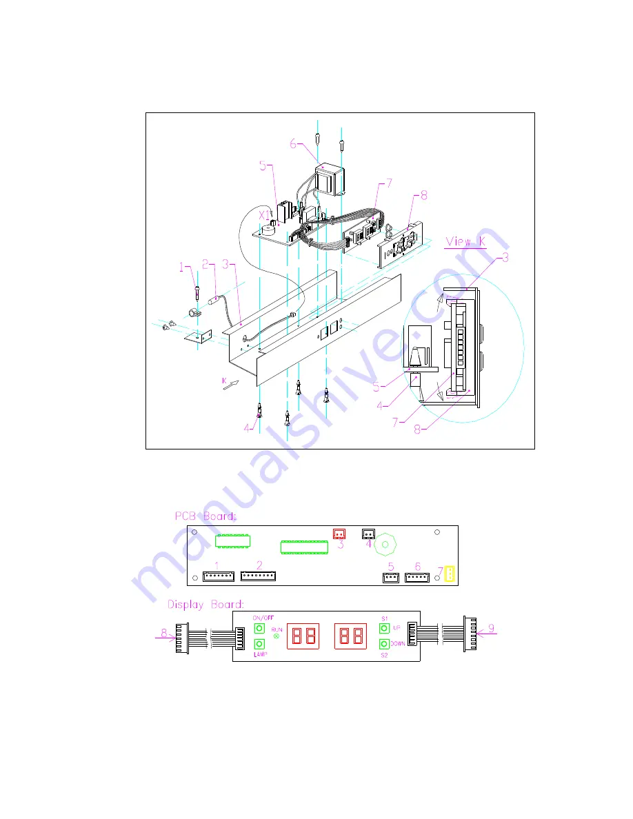
a. Remove the the shelf ,
( Fig.19)
b.Unplug all the connector, press the 4 studs
(
3
)
one by one. Updraw the control PCB board, and
draw off the PCB board, , replace it with the same model
’
s PCB board.
( Fig.19)
Fig.19
Fig.20
Diagram of the main PCB
( Fig.20).
1. To display PCB(connect to 8) 2. To display PCB(connect to 9)
3.To
evaporator sensor
(Red ) 4.To inner sensor(White)
5.To LED light
(
White
)
6.To power PCB (White )
7. To outer fan (Yellow)
B.How to replace the power PCB and transformer.


