22/23
1 >
.
After turning on the power, if the LED display shows the temperature is similar with the ambient
temperature, it is normal, if abnormal, please remove the electrical box
,
check the sensor insert
whether reliable
(Fig.11)
. If the insert is reliable, it is the sensor’s fault, remove the air-duct board
and replace the sensor with the same module
(Fig.1, Fig.2 ,Fig.3)
;
2 >
.
If the readout show E1, E2, it is the inner sensor open or short circuit default
(Fig.2.1)
, check the
circuit and repair it or replace the sensor.
(
Fig.14
,
Fig.14.1)
3 >
.
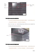
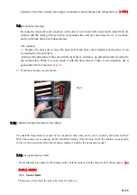
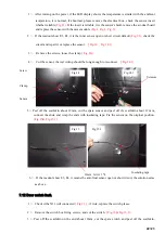
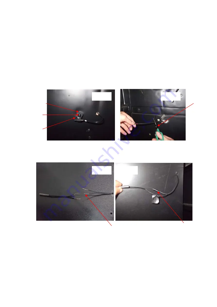
Remove the screws, loose the clamp
(
Fig.14)
;
4 >
.
Cut the sensor, the rest wiring should be long enough to reconnect.
(
Fig.14.1)
5>. Peel off the scarfskin about 12mm, cut the spare sensor and peel off it’s scarfskin about 12 mm,
connect the ends, and wrap the ends with insulating tape. Fix the sensor on the original position.
(Fig.15& Fig.15.1)
6 >
.
If the readout show E3, E4, it means the anti-frost sensor open or short circuit, the solution same
as above.
7.12 Door switch fault.
1 >
.
Check it the X11 will connected
(
Fig.11
)
, if it ok, replace the switch please.
2 >
.
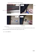
Remove the switch box fixing screws, and cut the switch.
(
Fig.16& Fig.16.1)
;
3 >. Peel off the scarfskin on the end about 12mm, cut the spare switch and peel off the scarfskin,
Screw
Fig.14
Fig.15
Fig.15.1
Sensor
Clamp
Scissors
Fig.14.1
12mm
(
strip
)
*4
Insulating tape


