background image

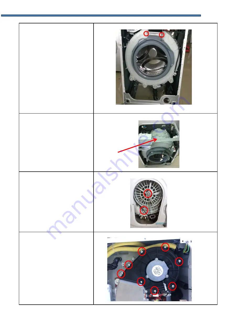
11.

Undo the gasket

I.

Undo the top cover, control 
panel, door lock, front 
panel. 

II. Undo 2 screws on clip

spring.

III. Loosen the inner gasket

clamp between the door
seal and the front of the
outer tub.

IV. Put the head of tunnel

assemble up, then take off
the gasket.

12.

Undo the top bracket

I.

Remove the control panel. 

II. Remove 4 screws fixing the

top bracket, and then
remove it.

13.

Undo the pulley

I.

Undo the back cover. 

II. Rotate the pulley and  at

the same time pull out the
belt.

III. Remove the screw on the

pulley and then take down
the pulley.

14.

Undo the fan motor 

I.

Undo 8 screws on the fan 
flange assembly and then 
take it down. 

DISASSEMBLY COMPONENT LOCATION


Summary of Contents for WDI3300

Page 1: ...Service Manual Washer Dryer Model WDI3300 ...

Page 2: ...the setting time 7 6 Water inlet overflow malfunction maintenance 7 7 Drum non rotating malfunction maintenance 7 8 Maintenance water inlet and water outlet at the same time 8 COMPONENT DATA 31 9 DISASSEMBLY COMPONENT LOCATION 32 9 1 Undo the back cover 9 2 Undo top cover 9 3 Undo the control panel and PCB 9 4 Undo the door assembly 9 5 Undo the front plate 9 6 Undo the detergent box 9 7 Undo the ...

Page 3: ...arning and precautions that are described on part labels and in the instruction book 1 2 2 Parts Assembly and Wiring Be sure to use insulation material such as tube and tape And be sure to restore all parts and wires to their original position Take special care to avoid contact with sharp edges 1 2 3 Perform Safety Checks after Servicing After servicing check to see that the screws parts and wirin...

Page 4: ...SEMBLE Indicates prohibition act must not be conducted Specific instruction is followed by a graphic or characters in or near DO NOT Symbol left warns not to disassemble UNPLUG Indicates forcing act must be conducted Specific instruction is followed by a graphic or characters in or near Symbol left warns to unplug the power cord Means secondary damages of property furniture domestic animal and pet...

Page 5: ... the washing machine Otherwise an electric shock or ignition may cause Sharing the same socket with other instrument causes heating of a branch socket and result in a fire CONNECT GROUNDING WIRE Connect the grounding wire Failing to do so may cause an electric shock when a short circuit occurs Consult an electric work shop or a sales shop DO NOT USE WET PLACE Do not install in a bathroom or a plac...

Page 6: ...standard Incorrect work causes an electric shock and a fire DO NOT PULL Do not pull the power cord when unplugging Hold the power plug to unplug An electric shock or short circuit may cause a fire DANGER HAND Do not insert your hand under the washing machine during operation There is a rotary part under the machine which may cause an injury WATER LEAKAGE Before starting washing open the faucet and...

Page 7: ... Rated Power 1900W Drying Power 1300W Rated Current 10A Max Spin Speed 1400RPM Display Type LED Motor BLDC Motor Energy Rating Energy Efficiency Class A Washing Performance Class A Spin drying Effiency Class A Energy consumption 5 44 Kwh Cycle Water consumption 124 L Cycle Specifications Net Dimensions W D H 595 565 815mm Net Weight 64Kg Gross Weight 68Kg 2 PRODUCT SPECIFICATIONS ...

Page 8: ...4 WIRING DIAGRAM PCB LAYOUT Warning care should be taken when diagnosing or replacing components as the appliance may store static electrical charge 4 2 The circuit program Inverter Motor ...

Page 9: ...ck Method Check Item t01 Version switchover 1 Press K6 button 2 Press K2 to change version 3 Press K1 button continuously for 3s to confirm your change LED displays 0xx x means current version t02 Error code checking 1 Press K6 button 2 Press K1 to show the last code and press K2 to show the next code 3 Press K2 and K3 button at the same time continuously for 3s after hearing the beep all the erro...

Page 10: ...e main wash level LED displays LL t07 Water temperature sensor and heater checking Press K6 button to activate the main inlet valve and get the water lever to heating level then turn on the heater and 5 mins later turned off automatically LED displays the current temperature t08 Inlet valve checking 1 Press K6 button LED displays uu and switch on the main wash inlet valve for 10 min 2 Press K1 but...

Page 11: ... 45r m clockwise for 15s and stop for 10s then rotates counterclockwise for 15s over and over again LED displays tUB t10 Spin speed checking Press K6 button the number on the display goes up in the same pace with the real speed and when it reach 400rpm you need to press K1 button to get the machine to reach its target speed LED displays spn ...

Page 12: ...pm fault alarm E6 E7 6 Drain test single drain if the water level is below 1 it is plus 40s malfunction alarm E3 7 Dehydration single dehydration judge whether the water level is below 1 if not drain water until it is below the 1 plus 20s then dehydrate in the maximum of speed unbalanced test is needless the maximum time is 10 minutes fault alarm E5 NOTE 1 The tests foregoing are reversible 2 It i...

Page 13: ...shing machine by PCB If the water level control switch is defective or more commonly if the small air pipe attached to the air bell restricted The switch will not be able to close the electrical contacts to the washer fill valve CHECK THE AIR PIPE CHECK THE WATER LEVERL SENSOR CHECK THE PCB and the inner wire between PCB and the sensor E12 The water level in drum exceed a certain level for alarm R...

Page 14: ...CB Check the PCB E30 Door will not open Door lock Check the door hook catch and the door lock to get correct location PCB If the washer door won t unlock the problem might be the main PCB This is not common Check the inner wire between the PCB and the door lock first E33 The PCB cannot detect the signal of the water level sensor Water level sensor Check the water level sensor Check the PCB the inn...

Page 15: ...line of the motor to prevent fall of 2 Check the PCB and the motor 3 Check the motor communicate wire E62 The speed don t transmit signal abnormality Triac get broken 1 Check the speed transmit line of the motor to prevent fall of 2 Check the PCB and the motor 3 Check the motor communicate wire 6 ERROR CODES AND EXPLANATIONS ...

Page 16: ...Temperature sensor Outlet and inlet are different with different model E38 In the drying process the temperature sensor at the air intake is wrong Temperature sensor Check the inner wire before replacing the Temperature sensor Outlet and inlet are different with different model Drying heater Push the red part of the temperature sensor before checking Check the inner wire on PCB Fan motor heater te...

Page 17: ...ult tree 1 Maintenance not heating malfunction Change the PCB Whether the connection is correct Reliable connection Whether NTC is short or open circuit Change NTC Not heating Change the heater Heater O C S C Y Y N Y N N Y ...

Page 18: ...ween the PCB and the door lock has loose wiring Reconnect and secure the PCB and door lock wiring Whether the door is closed correctly Close the door correctly Door not locking Broken or O C S C N Y Y N Change the door lock N Y Change the PCB Y 7 TROUBLE SHOOTING ...

Page 19: ...the standard Whether the tap is open Open the tap Whether the Drain Hose syphoning N N Check drain hose height N Y Whether the inlet filter net is blocked or hose kinked twisted Clean it with brush Refit hose Check wiring connection is correct on valve Y Y Reconnect and secure wiring N Valve O C N Change the inlet valve N Y Change the PCB Y Y 7 TROUBLE SHOOTING ...

Page 20: ...4 Over heating Change the NTC Over heating N Y Y Faulty O C S C Check resistance Change the PCB 7 TROUBLE SHOOTING ...

Page 21: ... time Whether the filter or pump is blocked Non drain or overtime drain Change the PCB Clean the filter pump N Y Y Change the drain pump N Pump O C N Whether the Drain Hose is syphoning or blocked Check the drain hose height blockage N Y 7 TROUBLE SHOOTING ...

Page 22: ...lfunction maintenance Valve faulty O C check resistance Change the PCB Whether the pressure switch is faulty check break after blow Change pressure switch Water inlet overflow Change the inlet valve Y Y Y N N 7 TROUBLE SHOOTING ...

Page 23: ...correctly Drum not rotating Installed the belt correctly The drum is blocked jammed Remove foreign object Refit secure wiring N Shut down the power open the door and Rotate the drum check the drum rotates freely N N Y Y Y Y 7 Drum not rotating malfunction maintenance 7 TROUBLE SHOOTING ...

Page 24: ... in the softener s box No fault the effect of the softener will not be affected Clean soap box drawer The washing machine does not fill Open the water tap Check the selection of the procedure Check the water pressure to see if the water pressure is insufficient Close the washing machine s door Check it the inlet water pipe is kinked or blocked The washing machine fills and empties at the same time...

Page 25: ...e detergent for the cylinder washing machine Reduce the usage amount of the detergent in the next times wash Soap box blocked The machine stops when the procedure has not been finished Power failure or water cut Check power supply fuse If you cannot solve the above abnormal situations would you please 1 To turn the procedure knob to OFF pull out the attachment plug 2 To close the water tap and con...

Page 26: ...resistance 2 seconds after the power supply can automatically locked 1 2 mins after the power off can automatically locked PASS 3 Water valve measuring resistance Resistance value range 3 6KΩ PASS 4 Pump Measure the resistance of the toroids Resistance value range 150 250Ω PASS 5 Heater measuring resistance Resistance value range 20 35Ω PASS 6 NTC measuring resistance Resistance value range 4 8kΩ ...

Page 27: ...mbly 5 Undo the front plate 6 Undo the detergent box 7 Undo the inlet valve 8 Undo the pressure switch 9 Undo the drain pump 10 Undo the pulley and motor 11 Undo the absorber pin from the cabinet 12 Undo the drum tub assembly 13 Undo the absorber pin from the drum 14 Undo the heater and NTC 9 DISASSEMBLY COMPONENT LOCATION ...

Page 28: ... fit back Cabinet II Push back the top cover 15mm until it leaves away from the control panel and then take it down 3 Undo the control panel I Remove the top cover plate II Draw out the detergent drawer III Loosen 2 screws on the control panel IV Loosen 2 screws on the control panel V Tilt the control panel and take it out 9 DISASSEMBLY COMPONENT LOCATION ...

Page 29: ...ck IV Take out the door lock and draw out the plug 6 Undo the front panel I Remove the top cover plate and the control panel II Remove the screw on the service plate box III Undo 5 screws on the front panel IV Remove the outer gasket clamp between the door gasket and the front plate V Take off the front plate 7 Undo the lower counterweight I Remove the front panel II Remove 4 screws and pull out t...

Page 30: ...lease the hose clamp and pull out the inlet hose III Release the hose clamp and pull out the detergent box hose and then take out the detergent box 10 Undo the water level sensor I Remove the top cover plate II Pull out the plug on the water level sensor III Loosen the water level sensor hose clamp and pull out the hose from the water level sensor IV Rotate the water level sensor anticlockwise by ...

Page 31: ...le up then take off the gasket 12 Undo the top bracket I Remove the control panel II Remove 4 screws fixing the top bracket and then remove it 13 Undo the pulley I Undo the back cover II Rotate the pulley and at the same time pull out the belt III Remove the screw on the pulley and then take down the pulley 14 Undo the fan motor I Undo 8 screws on the fan flange assembly and then take it down 9 DI...

Page 32: ...mp I Undo the front panel II Remove 4 screws unplug connector nip out the clamp between the drain hose and the drain pump and then pull out the drain hose 17 Undo the heater I Remove the rear cover II Remove the bolt and pull out the heater plug 18 Undo the NTC I Undo the heater II Undo the NTC with special tools 9 DISASSEMBLY COMPONENT LOCATION ...

Page 33: ...t lower counterweight detergent box the absorber pin water level sensor II Undo all connection between tub assemble and cabinet assemble III Push the rest down to front slowly and carefully IV Take off the cabinet from the tub assemble carefully 21 Undo the condesner assembly I Remove lid II Remove 2 screws on the clip spring III Undo 5 screws on fan ducting IV Undo 6 screws on the condenser V Und...

Page 34: ...ires and grounding wire II Use spanner to remove the motor screws and remove motor 24 Undo the rear tub assembly I Remove the motor II Pull out the heater III Remove the belt IV Remove the screws fixing the pulley and then take out the pulley V Remove the screws fixing the front and rear tub and then remove the tub VI Remove the inner drum kit 9 DISASSEMBLY COMPONENT LOCATION ...

Page 35: ...Open the door remove 2 screws fixing the hinge and the front panel and then remove the door II Remove 11 screws on the inner door III Undo the outer door and the inner door with special tool 9 DISASSEMBLY COMPONENT LOCATION I ...

Page 36: ...10 SERVICE TOOLS ...

Reviews: