19
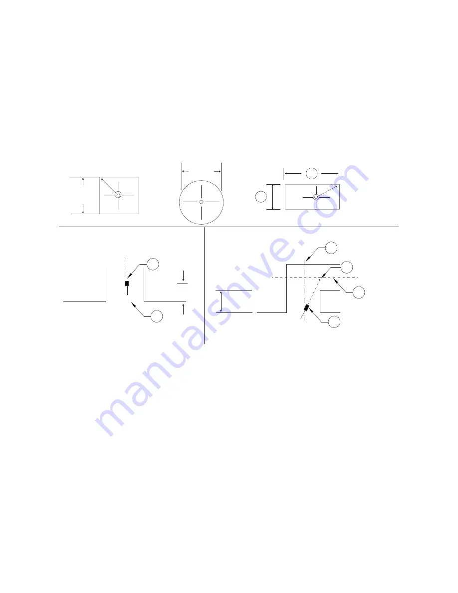
Nozzles must be installed from 0" to 6" into the protected area of the duct. When more than 1 ADP nozzle
is required (modular protection), each nozzle must be located at the center of its protected module area.
Additional nozzles are not required for changes in direction*. Duct obstructions and common ductwork
must be protected in accordance with this manual, NFPA 17A and NFPA 96.
ADP nozzle location and aim for duct protection are shown in
*When a change in direction occurs less than 6" from the duct entrance, the nozzle must be aimed as
Figure 21 - Single Nozzle Placement (0-50” Perimeter Duct)
• Duct perimeter up to and including 50” (1270mm).
• To determine the perimeter: 2(A) + 2(B) = 50” (1270mm).
1. ADP Nozzle
2. Horizontal Duct Centerline (CL)
3. Aim Point
4. Vertical Duct Centerline (CL)
5. Duct Entrance
A. Rectangular Duct Width
B. Rectangular Duct Length
B
A
CL
CL
CL
1
4
3
2
1
16” Nom.
(404mm)
12.5”
(318mm)
Max
0-6”
(0-152mm)
2-4”
(51-102mm)
Square Duct
Round Duct
Rectangular Duct
5
Vertical Duct
Vertical/Horizontal Duct
Summary of Contents for EWC
Page 2: ...2 ...


