background image

34

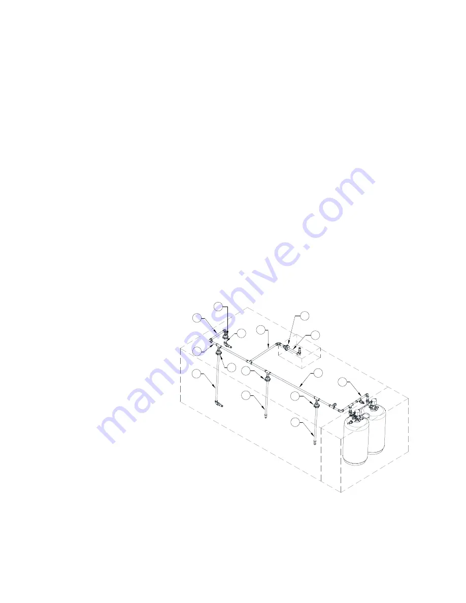
Agent Distribution Piping

The agent distribution piping shall be 3/8” NPT Schedule 40 black iron, chrome-plated or stainless-steel 

pipe and fittings. Fittings shall be minimum class 150. The pipe for the nozzle drops cannot be sleeved in 

steel but can be made from polished stainless steel, or polished chrome-plated black iron.
Galvanize pipe or fittings must not be used. Pipe thread or compound shall not be used.
Distribution piping can be run in single cylinder or dual cylinder, manifold configurations. Refer to 

page 35 

for single cylinder configuration details. Refer to 

page 37

 for dual cylinder configuration details. 

The distribution network consists of a supply line and all applicable branches depending on the protected 

hazards. Branch lines include the plenum branch, duct branch, overlapping nozzle appliance branch (TF1 

nozzle), and dedicated nozzle appliance branch (ADP). 
The supply line is defined as the run of all pipe and fittings from the tank outlet to the last branch line, 

including fittings at the start of all branch lines. All branch lines start at the outlet of the applicable supply 

line fitting and do not include the supply tee. 
A plenum branch is defined as the run of all pipe and fittings from the supply line tee outlet to the plenum 

nozzle(s). 
A duct branch is defined as the run of all pipe and fittings from the supply line tee outlet to the duct 

nozzle(s). 
An overlapping nozzle appliance branch is defined as the run of all pipe and fittings from the supply line tee 

outlet to the TF1 nozzle.
A dedicated nozzle appliance branch is defined as the run of all pipe and fittings from the supply line tee 

outlet to the ADP nozzle.

Figure 34 - Distribution Piping

1

3

3

2

2

1

2

5

4

4

3

3

6

6

3

1. Duct Branch Line
2. Supply Piping
3. Hood Penetrations
4. Overlapping Branch Line
5. Dedicated Appliance Branch 

Line

6. Plenum Branch Line

Summary of Contents for EWC

Page 1: ...and maintained in accordance with NFPA 17A NFPA 96 and the National Fire Code of Canada as applicable Installation and maintenance of the EWC extinguishing system must be performed in accordance with this manual by a factory trained and authorized distributor Improper installation poses serious risk of injury due to electric shock and other potential hazards Read this manual thoroughly before inst...

Page 2: ...2 ...

Page 3: ...ection Manual Actuation Device 43 Trouble Input Wiring 43 Battery Backup 44 Power Supply Adjustment 44 Fire Protection System Printed Circuit Board 45 ELECTRICAL 48 Wire Ampacity Rating 49 Distance Limitations 49 Fire Alarm Contacts 49 Fire Group 50 Fire Protection System Supervised Loops 51 OPERATION 52 Test Mode Overview 52 Reset Overview 53 TROUBLESHOOTING 55 Appliance Shutdown in Fault Conditi...

Page 4: ...replacement Equipment shall not be returned without MANUFACTURER S prior authorization and all returned equipment shall be shipped by the BUYER freight prepaid to a destination determined by the MANUFACTURER NOTE To receive warranty coverage for this product copy and print out the Start Up and Maintenance Documentation on page 76 Fill in all required information Fax the page to 1 919 516 8710 or c...

Page 5: ...ts 4 Cylinder Tanks Up to four tanks may be installed depending on cabinet size 1 2 3 4 2 1 Tank Mounting Brackets 2 Secondary Supervisory Pressure Switch Optional 3 Secondary Cylinder Optional 4 Primary Cylinder 5 Supervisory Pressure Switch Optional 6 Primary Actuator Kit 7 Secondary Actuator Hose Optional 8 Secondary Valve Actuator Optional 9 Primary Valve with Siphon Tube 10 Secondary Valve wi...

Page 6: ...e gauge indicator shown in Figure 3 should be in the acceptable green range for a cylinder that is properly pressurized and within the listed operating temperature range For a cylinder at the lowest listed operating temperature of 32 F 0 C the pressure gauge should read approximately 185 psig the lower end of the green range For a cylinder at the highest listed operating temperature of 132 F 54 4 ...

Page 7: ... secondary valve actuator during shipping and maintenance procedures Figure 4 Cylinder and Actuator Bracket Discharge Adapter The discharge adapter p n WK 283952 000 is used to connect the EWC cylinder valve outlet to the agent distribution pipe network The 1 2 inch NPT internal thread of the discharge adapter outlet is connected to the supply line via an elbow and adapter The discharge adapter us...

Page 8: ...lve into the primary actuator actuating the primary cylinder and into the interconnected secondary valve actuators actuating the secondary cylinders The primary actuator has a 1 8 NPT inlet port for connection to the primary system cylinder and a 1 8 NPT outlet port for connection to the secondary cylinder actuation line or actuation plug for single cylinder system The primary actuator includes a ...

Page 9: ...em pressure of 185 psig pressure at the lowest listed operation temperature of 32 F The supervisory pressure switch uses a diaphragm sensor to detect pressure changes At the pre determined set point the unit actuates a SPDT snap acting switch converting a pressure signal into an electrical signal The supervisory pressure switch can be used on primary and or secondary cylinders For primary cylinder...

Page 10: ...seal The foil seal prevents contamination from entering the pipe network and is designed to burst upon system discharge allowing the agent to flow to the protected hazard area Figure 9 Nozzles Vent Plug A vent plug p n 60 9196984 000 is installed in each agent distribution pipe network to prevent pressure build up caused by ambient temperature increases in the kitchen from rupturing the foil seals...

Page 11: ...he EWC extinguishing system The electric remote manual release is used to actuate the EWC extinguishing system manually and must be properly located and supervised in accordance with NFPA 17A and NFPA 96 Firestat Heat Detector The Firestat Fenwal Detect a Fire is a listed electric thermal detector available in a variety of temperature settings and used to actuate the EWC extinguishing system autom...

Page 12: ...noid valve is opened allowing pressure from the primary cylinder to flow to the primary and secondary cylinder valve actuators opening the cylinder valves and discharging EWC liquid fire suppressant to the protected hazard areas Figure 12 Cylinder Assemblies Cylinders Cylinders are typically factory installed pressurized and may be located anywhere within the hood end cabinet Additional cylinders ...

Page 13: ...tor Installation Figure 15 PAK in Ship Test and Installed Positions WARNING Do not complete PAK or secondary valve actuator installation until system test and commissioning are complete The cylinder bracket includes a platform for securing a primary actuator kit or secondary valve actuator during shipping and maintenance procedures The system actuators must be in the ship test position for all com...

Page 14: ...for installation of the SVA 2 Loosen the SVA shipping bolts from the top of the bracket slide the unit back and lower it into position on the valve actuation flange 3 Insert the mounting bolts through the bottom of the valve flange into the SVA mounting holes and tighten securely 4 Ensure the secondary actuator hose is securely connected to the primary actuator output port and SVA input port Key L...

Page 15: ...wn to 1mA at 24V DC Supervisory pressure switches are connected in parallel to the control panel supervisory input WARNING Proof pressure limits stated on the nameplate must never be exceeded even by surges in the system Occasional operation of unit up to proof pressure is acceptable e g start up testing Continuous operation should not exceed the designated over range pressure Proof pressure the m...

Page 16: ...s are added as required with each nozzle protecting no more than a 4 wide by 10 long plenum section ADP nozzles may be installed pointing in the same direction and or at opposite ends of the plenum pointing toward each other ADP nozzles must not be installed back to back when protecting plenum areas When positioned at the end of the plenum nozzles must be installed from 0 to 6 into plenum ADP nozz...

Page 17: ...r protection of ducts from 50 to 100 in perimeter and unlimited length A minimum of 3 ADP nozzles is required for protection of ducts exceeding 100 perimeter 32 nominal diameter and unlimited length When using multiple nozzles modular protection the coverage area for each nozzle must not exceed 50 perimeter Table 3 details the maximum rectangular duct configurations for one and two nozzle duct pro...

Page 18: ...0 39 11 38 12 37 13 36 14 35 15 34 16 33 16 8 32 17 2 31 17 7 30 18 1 29 18 5 28 18 9 27 19 3 26 19 7 25 19 9 24 20 2 23 20 5 22 20 8 21 21 Single Nozzle Duct Coverage 50 inches or less perimeter Side A Inches Maximum Side B Inches 21 4 20 5 4 5 20 5 19 5 5 5 19 6 18 5 6 5 18 7 17 5 7 5 17 8 16 5 8 5 16 9 15 5 9 5 15 10 14 5 10 5 14 11 13 5 11 5 13 12 12 5 12 5 ...

Page 19: ... are shown in Figure 21 and Figure 22 When a change in direction occurs less than 6 from the duct entrance the nozzle must be aimed as shown in Figure 21 and Figure 22 Figure 21 Single Nozzle Placement 0 50 Perimeter Duct Duct perimeter up to and including 50 1270mm To determine the perimeter 2 A 2 B 50 1270mm 1 ADP Nozzle 2 Horizontal Duct Centerline CL 3 Aim Point 4 Vertical Duct Centerline CL 5...

Page 20: ...hrough the exhaust ductwork as a means of pollution control Exhaust ductwork using ESPs requires ADP nozzle s upstream prior to and immediately downstream of the ESP The downstream nozzle s must be located centrally in the ductwork and should be aimed at the middle of the ESP Distribution piping to the ADP nozzles must not interfere with the function of the ESP unit A Pollution Control Unit PCU an...

Page 21: ...e appliance protection methodologies Overlapping Appliance Protection A single hazard zone utilizing overlapping coverage is 30 deep by the total length of the cooking surface of the protected appliances The cooking surfaces of all appliances protected by overlapping nozzles must be located within the defined hazard zones Cooking appliances eligible for overlapping protection are outlined in Table...

Page 22: ...he back of the hazard zone Tilt skillet coverage must not interfere with the edge of the nozzle discharge pattern 6 All appliance hazard surfaces must be located within the hazard zone 7 Smaller appliances can be positioned anywhere in the zone e g moved left right forward or backward provided the cooking hazard does not extend beyond the perimeter of the zone 8 When the depth of the appliance exc...

Page 23: ...med straight down The nozzle height must be 40 to 45 above the appliance cooking surface except for woks where height is measured from the inside bottom of the wok The nozzles must be positioned along the total hazard zone length to allow protection of each appliance in the hazard zone Overlapping Coverage Group Protection Overlapping protection provides coverage for a continuous hazard zone with ...

Page 24: ...eight requirements are based on the appliances protected for each individual zone A TF1 nozzle must always be located at the start and end of each zone no more than 12 from the end of the hazard zone edge of 1st last cooking appliance surface Refer to Overlapping Appliance Protection on page 21 12 Max ZONE 2 C C ZONE 1 A A B 12 Max 12 Max 12 Max D Overlapping Hazard Zone A Zone 1 Overlapping Nozzl...

Page 25: ...each individual zone A TF1 nozzle must always be located at the start and end of each zone no more than 12 from the end of the hazard zone edge of 1st last cooking appliance surface Refer to Overlapping Appliance Protection on page 21 A C 12 Max 12 Max 12 Max B 12 Max D ZONE 2 ZONE 1 DEDICATED APPLIANCE Overlapping Hazard Zone A Zone 1 Overlapping Nozzle Spacing B Zone 1 Overlapping Nozzle Height ...

Page 26: ...protected for each individual zone A TF1 nozzle must always be located at the start and end of each zone no more than 12 from the end of the hazard zone edge of 1st last cooking appliance surface Refer to Overlapping Appliance Protection on page 21 A 12 Max 12 Max A 12 Max C C D B ZONE 2 ZONE 1 12 Max Overlapping Hazard Zone A Zone 1 Overlapping Nozzle Spacing B Zone 1 Overlapping Nozzle Height C ...

Page 27: ...nsions 4 Ranges may have an integral back shelf or obstruction that protrudes more than 11 inches from the back edge of the cooking surface at a minimum height of 18 inches above the cooking surface The cooking surface of the range is defined as the overall burner grate dimensions 5 Additional nozzles must be added for appliances that exceed the maximum hazard dimensions for the specified nozzle s...

Page 28: ...artment near the front opening and aimed through grill toward center of grease drain opening Discharge shall not be obstructed by any structural part of the broiler NOTE Appliance Drop Fittings Must Not be Sealed with Pipe Dope or Teflon Tape Figure 27 Broiler Salamander Protection Cooking Appliance Cooking Appliance ADP Nozzle Union for Pipe Top 4 of Broiler Compartment ...

Page 29: ...1 back from the opening aimed at the opposite back corner Nozzle 2 centered over top opening mounted 12 to 48 above the top of the appliance Discharge shall not be obstructed by any structural part of the broiler NOTE Appliance Drop Fittings Must Not be Sealed with Pipe Dope or Teflon Tape Figure 29 Open Top Chain Broiler NOZZLE CENTERED VERTICALLY IN OPENING ABOVE CHAIN TOP OPENING SECOND NOZZLE ...

Page 30: ...t be Sealed with Pipe Dope or Teflon Tape Figure 30 Charcoal Charbroiler AN ADP NOZZLE MAY BE LOCATED ANYWHERE WITHIN THE GRID DIAGONAL FROM AIM POINT 48 in 1219 mm MAX 48 in 1219 mm MAX 48 in 1219 mm MAX 24 in 610 mm MAX 24 in 610 mm MAX 24 in 610 mm MAX 6 in 152 mm MAX FUEL AIM POINT MIDPOINT OF HAZARD AREA AN ADP NOZZLE MAY BE LOCATED ANYWHERE WITHIN THE GRID AIM POINT MIDPOINT OF HAZARD AREA 2...

Page 31: ... using 2 nozzles All dimensions fixed unless otherwise noted e g min max NOTE Appliance Drop Fittings Must Not be Sealed with Pipe Dope or Teflon Tape Figure 31 Range Top with Shelf 1 ADP Nozzle 2 Shelf 11 maximum distance from the rear edge of the cooking hazard to the front edge of the shelf 3 Distance from rear edge of cooking hazard to aim point on the cooking surface of the nozzle is 4 5 4 To...

Page 32: ...e noted e g min max NOTE Appliance Drop Fittings Must Not be Sealed with Pipe Dope or Teflon Tape Figure 32 Range with Obstruction Notes When protecting ranges in accordance with these low proximity recommendations the following minimum pipe requirements must be met to prevent splash Minimum of 16 of pipe 1 tee 4 elbows prior to the first R nozzle protecting a low proximity range Minimum 6 5 of pi...

Page 33: ...ow appliance coverage for Upright Broiler Salamander Protection on page 28 All dimensions fixed unless otherwise noted e g min max NOTE Appliance Drop Fittings Must Not be Sealed with Pipe Dope or Teflon Tape Figure 33 Range with Upright Obstruction Notes When protecting ranges in accordance with these low proximity recommendations the following minimum pipe requirements must be met to prevent spl...

Page 34: ...h TF1 nozzle and dedicated nozzle appliance branch ADP The supply line is defined as the run of all pipe and fittings from the tank outlet to the last branch line including fittings at the start of all branch lines All branch lines start at the outlet of the applicable supply line fitting and do not include the supply tee A plenum branch is defined as the run of all pipe and fittings from the supp...

Page 35: ...ch above supply line 5 Maximum 6 75 ft linear pipe between two most remote branch tees on supply line 6 Minimum 7 ft pipe and 3 elbows before a range w o shelf or fryer to prevent splash 7 Minimum of 7 ft pipe and 2 elbows before a wok to prevent splash Furthermore a total of 10 ft pipe 6 elbows and minimum of 4 flows are required in the complete pipe network 8 Minimum 7 ft pipe and 2 elbows befor...

Page 36: ...ed ADP appliance branches per the above table provided the individual branch limitations are maintained per the UL ULC listed limits e g max 3 pipe max 2 elbows for an individual duct plenum branch 6 The R nozzle provides a wider spray angle than the ADP nozzle the nozzles are identical in flow points and flow rate Therefore the R nozzle may be used as a substitute for the ADP nozzle for low proxi...

Page 37: ...aximum 2 ft vertical rise of duct or plenum branch above supply line 5 Maximum 13 5 ft linear pipe between two most remote branch tees on supply line 6 Minimum 7 ft pipe and 3 elbows before a range w o shelf or fryer to prevent splash 7 Minimum of 7 ft pipe and 2 elbows before a wok to prevent splash Furthermore a total of 10 ft pipe 6 elbows and minimum of 4 flows are required in the complete pip...

Page 38: ...he above table provided the individual branch limitations are maintained per the UL ULC listed limits e g max 3 pipe max 2 elbows for an individual duct plenum branch 6 The R nozzle provides a wider spray angle than the ADP nozzle the nozzles are identical in flow points and flow rate Therefore the R nozzle may be used as a substitute for the ADP nozzle for low proximity range protection Table 11 ...

Page 39: ... without Teflon tape or pipe compound 2 Ensure nozzles are securely installed DO NOT OVERTIGHTEN 3 Ensure nozzle seals are properly oriented in the nozzle cap The seal must be installed with the brass retaining ring attached to the foil seal facing towards the nozzle 4 Ensure nozzle caps and foil seals are installed on each nozzle and secure Nozzle caps should be wrench tightened 1 4 to 1 2 turn p...

Page 40: ...gas valves 3 4 2 can be mounted with the solenoid in any position above horizontal 120V AC gas valves 2 1 2 3 must be mounted with the solenoid vertical and upright The pipe must be horizontal All 24V DC gas valves must be mounted with the solenoid vertical and upright The pipe must be horizontal Proper clearance must be provided in order to service the strainers A minimum of 4 clearance distance ...

Page 41: ...sensor installed for every 12 feet of hood length Multiple sensors are wired in parallel in the supervised loop The Firestat may be installed on the opposite side of the quick seal for access in the duct Non Solid Fuel Appliances Rated 450 F Non solid fuel appliances rated for 450 F will not require additional firestats regardless of the configuration and length of ductwork Non Solid Fuel Applianc...

Page 42: ...Open Close on Rise 360 F 2 32 00002 1 2 NPT Quik Seal Adapter Body 3 32 00002 1 2 NPT Quik Seal Gasket 4 N A Hood Duct External Surface 5 N A 1 1 8 1 1 4 Diameter Hole 6 32 00002 1 2 NPT Quik Seal Lock Washer 7 32 00002 1 2 NPT Quik Seal Nut 8 59361 1 2 Extension Ring 9 100 BW Extension Ring Cover 10 N A 2 White Wires 11 N A 2 Black Wires 1 2 4 5 7 6 8 9 3 10 11 ...

Page 43: ...latch is released The clear protective cover must be installed to protect the device from accidental activations This cover is provided as part of the manual actuation device Below are the part numbers for the devices and replacement parts Note When connecting the wires to the push pull station do not twist the wire ends together Insert each wire on the opposite side of the screw Trouble Input Wir...

Page 44: ...teries are lead acid type and are recyclable please dispose of the old batteries properly During extended periods of inactivity where the fire protection system will be without AC power for more than 2 days such as a shutdown or natural disaster it is best to decommission the fire system by disconnecting the batteries This will prevent any damage to the batteries through complete discharge When th...

Page 45: ...y If a fault is detected anywhere in the system an audible alarm will periodically sound and the Fire System Activated light will flash a fault code to indicate the fault that was detected This fault code consists of a series of flashes followed by a pause Simply count the number of flashes between the pauses and refer to the chart below to find the cause of the fault Any fault is extremely import...

Page 46: ... 8 and Pin 9 24V DC Input Shutoff Valve Supervision Pin 10 N A Pin 11 Drive Output Fire Relay Pin 12 Drive Output 100 Relay Pin 13 Drive Output Trouble Relay Pin 14 Drive Output Wash Relay Pin 15 Drive Output Spare Relay Pin 16 Drive Output Auto Man Relay Connector J4 contains Power Supply and Device connections Pin 1 Positive Input Power Supply Pin 2 Output Panel Mounted Audible Alarm Pin 3 Outpu...

Page 47: ... Signal B Connector J8 Interlock Network connections Factory Use Only Connector J9 Building Fire Alarm connections for a set of normally open dry contacts These are provided for signaling a building fire alarm panel if a fire condition is present Pin 1 Dry Contact Closure Pin 2 Dry Contact Closure Connector J9 Building Fire Alarm connections for a set of normally open dry contacts These are provid...

Page 48: ...ed to be wired The temperature sensor must be wired to terminal blocks as indicated on the wiring schematic 8 If the system contains additional firestats they must be wired into the supervised loop 9 If the control is a wall mount system the hood lights wiring will need to be wired to terminals B and W Verify connections on wiring schematic 10 Before powering up the system make sure that the inter...

Page 49: ...e protection system control package and a gas valve Refer to Table 16 for maximum wiring distance between the system and remote gas valve Fire Alarm Contacts The fire protection system is equipped with normally open contacts that can be connected to the premise Fire Alarm Control Panel FACP terminals AL1 and AL2 During a fire condition the contacts will close and trigger the premise FACP to initia...

Page 50: ...are assigned on the CORE boards and if a fire condition exists in any one group it will NOT activate the other fire group although both are connected to the same interlock network Fire Group 01 CORE board DIP switch setting will be set to Switch 6 Open and Switch 7 Open Fire Group 02 CORE board DIP switch setting will be set to Switch 6 Closed and Switch 7 Open Refer to Typical DIP Switch Arrangem...

Page 51: ...for an outgoing loop Flexible metallic conduit is used to route the wiring that connects the firestat to the remote loop junction box Secure conduit to hood hat channel when possible The system contains two circuit ceramic terminal blocks for connecting from one hood to the next Figure 44 Supervised Loop Connections For connections on or above the hood use Type MG or MGT wiring with High Temperatu...

Page 52: ... control panel simultaneously shuts down all gas and electric appliances under the protected hood s shuts down make up air and or exhaust where applicable and activates the building fire alarm where applicable A means of manual reset is required for shut off devices to ensure manual reset prior to fuel or power being restored in accordance with NFPA 17 and NFPA 96 The electric gas shut off valve i...

Page 53: ...KA SVA refer to Disconnecting Service Tank Re arming System on page 62 Note The firestat must be cool and the remote manual actuation device push pull station must be reset for this button to work The fire system must be re commissioned per the manufacturer s recommendations and guidelines by an authorized fire system distributor and or authorized service agent After a fire full inspection by a ce...

Page 54: ...t off devices All wiring must be in accordance to NFPA 70 and the Authority Having Jurisdiction AHJ When a building fire alarm system is present the fire alarm control panel must be connected in accordance with the NFPA 72 such that the actuation of the EWC extinguishing system also activates the fire alarm Reference the applicable control panel manual for wiring and compatibility Figure 46 Reset ...

Page 55: ...rify fire is out and reset fire system A fault code is flashing on the Fire System Activated light A fault has been detected in the Fire Protection System Count the flashes and refer to Table 20 Fire System will not turn off Duct sensor is hot Heat has activated the duct sensor Remove heat source or let the system extinguish the fire Once heat source or problem is resolved press reset button on th...

Page 56: ...s shutting down for 15 minutes However once the fire system is activated the shunt trip electric appliances and the gas valve will be locked out until test mode is deactivated During AC power failure all gas appliances will be shut down Electrical appliances will shut down on building power loss Table 20 Appliance Fault Conditions Number of Flashes Fault Condition Gas Valve Shut Down Shut Down Shu...

Page 57: ... 1 8V Supervised Loop Fault Open Supervised Loop between Terminals 21 and 24 Locate and repair faulty wiring in the 21 24 supervised loop Terminal 22 to CORE Power Supply 0V Terminal 23 to CORE Power Supply 0V Terminal 23 to Terminal 24 26 5V Open Supervised Loop between Terminals 22 and 23 Locate and repair faulty wiring in the 22 23 supervised loop Terminal 101 to CORE Power Supply 26 5V Termina...

Page 58: ...will broadcast the notification every 2 seconds until the condition is cleared When the supervisory fault condition is cleared 10 notifications will be sent one every 2 seconds Table 21 DIP Switch Settings DIP Switch Description 1 through 4 DIP Switch Position Interlock Network Address 1 2 3 4 Closed Open Open Open 1 Open Closed Open Open 2 Closed Closed Open Open 3 Open Open Closed Open 4 Closed ...

Page 59: ... 6 DIP 7 DIP 8 1 Hood Master Closed Open Open Open Closed Open Open Closed Core Board DIP 1 DIP 2 DIP 3 DIP 4 DIP 5 DIP 6 DIP 7 DIP 8 1 2nd Hood Slave Closed Open Open Open Open Open Open Closed 2 Hood Master Open Closed Open Open Closed Open Open Closed Core Board DIP 1 DIP 2 DIP 3 DIP 4 DIP 5 DIP 6 DIP 7 DIP 8 1 PCU Slave Closed Open Open Open Open Open Open Closed 2 Hood Master Open Closed Open...

Page 60: ...ion quickly to minimize nitrogen loss 2 Verify that the Supervisory Pressure Switches have activated 3 Remove the PAK and any Secondary Valve Actuators SVA from their cylinder Place PAK and SVAs in the ship test position Verify that the PAK and SVAs are securely mounted to the bracket Refer to Figure 15 on page 13 4 Connect the stainless steel hose from the PAK assembly to a Nitrogen Service Cylin...

Page 61: ...ch or flame is strictly prohibited Method 2 Lift the cover to the manual release station and push the manual release station button to activate the fire system The manual release station can be re set by twisting the push button in a clockwise motion 6 Verify that the control panel has activated and that the audible alarm is sounding 7 Ensure the PAK and all SVAs have actuated with the piston in t...

Page 62: ... If a PAK or SVA fails to operate or cannot be properly reset the unit must be replaced Refer to MAINTENANCE on page 63 for replacement procedures 6 If all of the above is confirmed secure the 1 4 plug on the last fire system actuator Verify all of the actuation lines between the PAK and SVA s are secure and tight Place Schrader Valve caps onto service ports and tighten 7 Install the PAK and any S...

Page 63: ...e noted while making this inspection DO NOT CONTINUE OPERATING COOKING APPLIANCES Immediately contact an authorized distributor for service and or repair The following procedure is to be performed by the Owner of the system on a monthly basis Table 22 Owner s Monthly Maintenance Checkbox Procedure Verify the extinguishing system is in its proper location Inspect all system components agent distrib...

Page 64: ...y aimed secured and located within the proper distance from the protected equipment Each nozzle should be clean and equipped with a foil seal cap All piping joints and pipe supports are securely fastened The pipe lengths sizes fittings and material are as specified in this Manual All wiring is in compliance with local codes All field wiring is free of ground fault or short circuit conditions All s...

Page 65: ...ve 6 If applicable remove the side plug on the PAK and install in the secondary actuation hose 7 Install the supervisory pressure switch onto the new PAK Replacing A Secondary Valve Actuator If an SVA fails to operate during system testing follow these steps to replace the SVA 1 Ensure the primary actuation hose is not connected to the primary cylinder or a nitrogen pressure supply system 2 Discon...

Page 66: ... down Wear rubber gloves and eye protection while cleaning If skin or eyes come in contact with the agent flush thoroughly with water Cleaning Distribution System The EWC extinguishing system must have all discharge piping and nozzles flushed out with water after any discharge as detailed in the following procedures Cleaning Nozzles 1 Remove all nozzles from the system 2 Inspect each nozzle filter...

Page 67: ...a Cylinder on page 74 8 Attach a suitable container or hose to a container or other point of disposal at each pipe outlet where a nozzle was installed to collect the water discharge 9 Install the PAK Refer to Primary Actuator Kit PAK on page 14 10 Install the SVAs onto their respective cylinders Refer to Secondary Valve Actuator on page 14 11 Re arm the control panel by placing the package in arme...

Page 68: ...ll excess water Disconnect the nitrogen service tank 11 Install new or recharged cylinders at each cylinder location 12 Re install vent plug 13 Re install nozzles ensuring that all nozzles are in the correct location and properly aimed Refer to Nozzles on page 39 for nozzle placement and aim directions 14 Complete the Start up Test Procedure Refer to Start up Test Procedure on page 60 Cylinder Mai...

Page 69: ...condary cylinders are present remove the mounting bolts connecting the Secondary Actuators to the secondary cylinders Lift the actuators up and place the actuators into the bracket Ensure they are supported by the shipping bolts Install the Valve Protection Plates on top of each secondary cylinder s valve using the mounting bolts and 2 nuts Refer to Figure 50 8 For each secondary cylinder perform ...

Page 70: ...upply 13 Carefully open the discharge valve 14 Monitor the discharge to prevent spillage and to ensure that the hose remains secure 15 Control the rate of discharge via the ball valve 16 If applicable stop the flow and change containers 17 When the discharge is complete turn off the nitrogen service cylinder supply 18 Check that the cylinder gauge indicates no pressure and carefully depress the Sc...

Page 71: ...of the valve 11 Place the valve onto a 3 4 pipe section spare socket or equivalent to keep valve stem from falling out 12 Insert a new valve spring onto the top of the valve stem 13 Place a new spring retainer onto the valve spring 14 Press the retainer down on the valve stem and install a new retaining ring check onto the valve stem using the bent tip snap ring pliers 15 Ensure the retaining ring...

Page 72: ...tempt to recharge any cylinder without first checking for most recent hydrostatic test date In accordance with DOT and TC regulations the EWC wet chemical cylinder must not be recharged or transported without first being inspected internally and externally and hydrostatically tested if more than 5 five years have elapsed since the date of the last hydrostatic test Regardless of previous inspection...

Page 73: ...efer to Figure 53 6 Pressurize the cylinder with nitrogen to 200psig at 70 F Refer to Table 23 for pressure variation with temperature 7 Turn off nitrogen supply and disconnect cylinder 8 Remove the discharge adapter 9 Check for leakage using a soap solution 10 Immediately install the Anti Recoil and Valve Protection Plates until the cylinder is ready to be installed Refer to Installing Valve Prot...

Page 74: ...fer to Figure 50 Installing a Cylinder All removed cylinders must be replaced with new fully charged or properly re charged cylinders Follow these steps to install a cylinder 1 Lubricate a new O ring with Parker Super O Lube and install on the discharge adapter 2 Remove the anti recoil cap and place the cylinder into position ensuring a tight seal with the discharge adapter 3 Strap the cylinder on...

Page 75: ...as Shut off Valve 1 ASCO 8214250 A0024937 Gas Shut off Valve 1 1 4 ASCO 8214265 A0024938 Gas Shut off Valve 1 1 2 ASCO 8214275 A0024939 Gas Shut off Valve 2 ASCO 8214280 A0024940 Gas Shut off Valve 2 1 2 ASCO 8214290 A0024936 Gas Shut off Valve 3 ASCO 8214240 A0024935 Table 25 Maintenance Recharge Description Part Number A X Number Valve Protection Plate WK 255096 000 A0030739 Anti Recoil Plate WK...

Page 76: ... BE PERFORMED AFTER THE SYSTEM HAS BEEN INSTALLED Warranty will be void without completion of this form Job Information Cleaning and Maintenance Record Notes Job Name Service Company Address Address City City State State Zip Zip Phone Number Phone Number Fax Number Fax Number Contact Contact Purchase Date Start Up Date Date Service Performed ...

Reviews:

Related manuals for EWC