background image

Survey - the essentials

14

The unit is as simple as we could make it in terms of setting-up and flying. 

However, if you are a beginner to helicopters it is really essential to ask a friend 

with experience of flying these machines to help you at the initial test-flying 

stage, as the functions of a helicopter are very complex. 

This double page and all the points marked with an exclamation mark  


are particularly important, and should be read carefully even by pro-standard 

pilots.


Installation

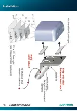
  Mount  only  by  using  the  supplied  self-adhesive  soft  foam  stripes,  strictly 

  according to the instructions (pages 16-18).

 An electrical connection must be created as an earth between the tail boom,  

  the motor crankcase and the helicopter chassis.

 The higher in the model the unit is installed, the smoother the stabilisation in  

  position mode when close to the ground.

 Please ensure that the unit is set vertically, securely fixed in the model, and  

  with an absolutely unobstructed view between the sensor and the ground.

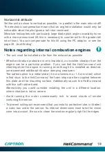
 Important  notes  for  internal-combustion  helicopters  and  comprehensive  

  installation tips: see page 19.

Transmitter 

All the mixer functions for elevator, aileron and tail rotor must be disabled: al-

ways set single-servo mode (H1 or CCPM), as the 

HeliCommand

 is designed 

to use its own internal mixer exclusively.

Configuration

The unit must be configured in order to match it to the model and the   

RC system; this only needs to be carried out once (page 23). 

If the standard default settings suit your model and RC system (page 22) this 

setup can be omitted.
Before the first flight with the system it is essential to check the controls and 

sensor directions on all three axes! (page 28)

Summary of Contents for HeliCommand 3A 3D RIGID

Page 1: ...INSTRUCTIONS M SERIES ...

Page 2: ...2 www helicommand com ...

Page 3: ...with the HeliCommand If you are a beginner the HeliCommand will enable you to hover the heli copter carry out slow circuits and generally practise more easily However one point which should be addressed here is that the pilot must be attentive and should not let this unique system seduce him into trying manoeuvres which could endanger himself or others Also it is ideal for advanced pilots who are ...

Page 4: ...adio link fails PPM FM only switches to position stabilisation coll pitch to hold Suitable for internal combustion and electric powered helicopters Can be used indoors and in the open air PC adaptor available as accessory for setup of 4 head servos optimisation for stabilisation and tail gyro and additional options like automatic trim freewheel function for forward flight etc HeliCommand 3D Includ...

Page 5: ...functions Expanded mixer options Virtual swashplate rotation and sinus compensation matches unequal pushrod travels caused by the tilting of servo arms The pilot channel can be used to select horizontal mode position mode RIGID mode RIGID and horizontal modes even function without visual contact between the optical sensor and the ground i e no opening is required in the helicopter fuselage if you ...

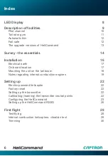
Page 6: ...board location 17 Mounting the unit on the tail boom 18 Notes regarding internal combustion engines 19 Setting up 22 Electric powered helicopter 22 Factory reset 22 Setting up the transmitter 22 Calibrating learning the transmitter neutral points 22 Configuring the HeliCommand 23 Setting up the HeliCommand RIGID 26 First flight 28 Test flying 28 Internal combustion helicopters vibration test 29 Tr...

Page 7: ...r flying 33 Checking the contrast 33 Versions and applications 34 HeliCommand 3A 34 HeliCommand 3D and above 34 3D manoeuvres 34 HeliCommand RIGID 34 Notes 35 For skilful pilots differences in handling 35 Range of applications 35 Safety measures We recommend 36 Liability exclusion Guarantee 37 Fault finding 38 Specification Set contents 40 Accessories Service Imprint 41 ...

Page 8: ...Kanal and assigned via PC adaptor Setup process step number count of flashing Fault at selftest LED flashes red No output of servo signals 1x 2x 3x 4x 5x 6x 7x 8x No during selftest Battery 4V power up Movement during power up phase repeat power up Instruments fault or too extreme temperature Auto trim value at the limit reserved Unacceptable center divergence at automatic learning process at leas...

Page 9: ...is the collective pitch throttle function If the model exhibits any slow drift at the hover this can very easily be corrected manually For slow circuits close to the ground you can set a forward speed by keeping a slight constant push on the elevator stick then direct the model using the tail rotor stick just like steering a car For higher speed and for flying at heights above about 5 m this mode ...

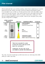
Page 10: ...the pilot channel is not connected to the recei ver a pre set value applies which is position mode with a setting of 70 this is a suitable setting for many models and can be changed to any value you like using the PC adaptor You may of course exchange up with down side by reversing transmitter setting or slider mounting Slider more towards the center reduces the sensor gain and slows down the corr...

Page 11: ...ng the PC adaptor Further adjustments can be made using the PC adaptor e g travel limiting and collective pitch tail rotor mixing the latter is mixed in after the gyro and therefore also works in heading lock mode The versions 3D and Rigid provide additional expert adjustments e g delay and hold range If you do not wish to use the integral gyro an external gyro can be connected directly to the rec...

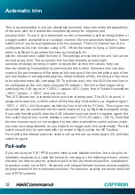
Page 12: ... then triggered by switching the AUX signal to 100 approx 60 note that in Futaba transmitters 100 means 100 and vice versa The LED flickers red to indicate while auto trim is being sent The AUX channel if assigned to auto trim will still switch off the heading hold mode by a negative signal 100 60 but Gyro gain sensitivity has to be set by PC only Thus a gyro mo de switch can be combined into the ...

Page 13: ...s on flying page 32 HeliCommand RIGID If your rotor head has no flybar you must use the HeliCommand RIGID and you must activate RIGID mode If not the stabilisation may not work properly due to the occuring turn rates All the RIGID Mode set up functions can be accessed using the PC adaptor they are explained in detail in the HeliCommand set up software once you have selected HeliCommand RIGID as th...

Page 14: ...higher in the model the unit is installed the smoother the stabilisation in position mode when close to the ground Please ensure that the unit is set vertically securely fixed in the model and with an absolutely unobstructed view between the sensor and the ground Important notes for internal combustion helicopters and comprehensive installation tips see page 19 Transmitter All the mixer functions ...

Page 15: ... position mode is switched on as occasional drift or interference influences may occur at any time without warning Indoor flying please be sure to read the notes on page 33 Do not fly inverted or attempt aerobatics 3D with the 3A version see page 34 Models without a flybar can only be stabilised using the RIGID version and only then if RIGID mode is activated see page 34 Even though the system inc...

Page 16: ...Installation 16 ...

Page 17: ...racket supplied the tail boom the tail rotor servo the chassis or the fuselage nose Installed attitude Vertical with optical sensor facing down Any of the four possible directions can be used Unobstructed view between the sensor and the ground The cross section of the vision cone is square with an open angle of 15 x 15 For this reason you must arrange an unobstructed square vertically below the se...

Page 18: ...on relative to the boom using UHU hart or cyano acrylate glue Double sided foam tape is too soft for this purpose Protect from vibration Please take particular care to protect the unit from vibration Always use the supplied special soft self adhesive foam tape and only two nar row strips right along the top and bottom edges of the back panel This means that the mounting surface must be at least as...

Page 19: ...from the engine can be a particular problem If you can feel the HeliCommand unit vibrating when the engine is running even though it is installed as directed we recommend additional vibration damping measures The safest option is a metal plate 3 mm aluminium or 1 5 mm steel which is first stuck to the HeliCommand the foam strips are then applied between this plate and the mounting surface Addition...

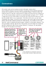
Page 20: ...ntees that the signals from the auxiliary channel sliders and switches are also transferred without any mixing Attention if using an H4 swashplate linkage the PC adaptor is necessary Connections aileron roll elevator coll pitch tail yaw PILOT AUX 90 with 45 offset battery aileron roll elevator coll pitch tail servo H1 single servo RC Modul receiver SET LED serial interface left front right back le...

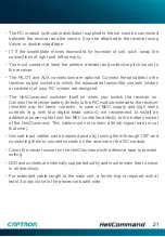
Page 21: ...eceiver on Connect the receiver battery directly to the RC module instead to the receiver shortest way for servo currents In case of BEC supply and high servo currents e g with four digital head servos we recommend to install an additional power cable from the BEC controller directly to the battery socket of the HeliCommand This cable must not contain a third signal wire or cut that wire Unused in...

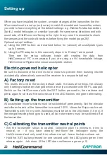
Page 22: ...ife accidentally alternatively connect the receiver to a separate battery A Factory reset This resets the unit to the factory default state It erases all settings Necessary only if settings had been changed which are only accessible with the PC adaptor Switch on the HeliCommand with the SET button pressed in then release and press again for at least five seconds until the LED flashes red green alt...

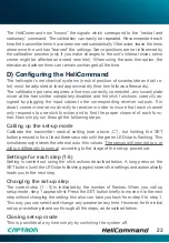
Page 23: ...nsure that each channel only responds to one stick function and to find the proper channel of each func tion Now simply run through the following steps Calling up the set up mode Calibrate the transmitter neutral setting see above C but holding the SET button pressed in for at least three seconds until the green LED starts flashing This simultaneously erases the internal auto trim values The servo...

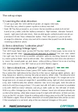
Page 24: ...ut tilting Store the correct setting with a long press on the SET button until LED flashes again 3 Servo directions elevator and aileron The LED must flash three times press SET button briefly if necessary Now select the right elevator function from the two or eight possible options wor king forward or back by moving the aileron stick to either side The elevator stick should tilt the swashplate ev...

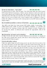
Page 25: ...ame direction as the direction of rotation of the main rotor viewed from above and store it with a long press on the SET button until LED flashes again Concluding the setup Switch on again keep unit still during power up and check the controls Set any travel reductions at the transmitter to prevent mechanical fouling and set the correct collective pitch range because travels may now be different t...

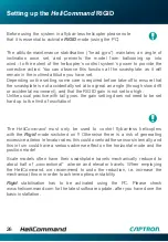
Page 26: ...e RIGID gain is not set too high Unlike usual practice with tail gyros the gain setting does not need to be set hard up to the limit of oscillation The HeliCommand must only be used to control flybar less helicopters with the Rigid mode switched on Otherwise there is a risk of generating excessive aileron elevator rates this could overload the sensors internally and this in turn could have a serio...

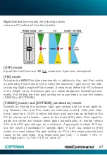
Page 27: ...se the modes FADER or EXTREME FADER scale and EXTREM aerobatics mode Suitable for finding the optimum rigid gain setting and for more agile fly ing Disables Hor and Pos mode conventional control With pilot chan nel at travel end 100 in either direction gain becomes as defined at the PC for aileron and elevator same as the mode FIX does Pilot signal to wards the centre will reduce these gains propo...

Page 28: ...ry out a range check with the transmitter aerial collapsed Test flying If you are a beginner we recommend that you ask a modelling friend with experience of helicopters to check the settings and help you with the first flight Notes on trimming see pages 12 30 At take off Prior to take off the helicopter should be standing as level as possible If you have to hold the helicopter inverted or at a ste...

Page 29: ...ry movements may occur This applies in particular when the distance between the sensor and the ground is very small 0 5 m Set the gain so that optimum stabilisation is achieved in the green Pos mode at an altitude of about 0 5 m If oscillation occurs reduce If drifting uncontrolled increase With tail rotor gyros it is usual practice to set the gain hard up against the limit of oscillation but this...

Page 30: ...hen using auto trim This can be done with the model on ground While in heading hold mode trim the transmitter so that the tail servo which can remain in various positions stays in the centre without drifting off by itself This tail trim is not affected by the SET button SET only calibrates roll and elevator If during flight the tail responds un equal at both directions the best way is to adjust th...

Page 31: ... to have been in an approximately steady flight state for about eight seconds before you do this The trim always refers to the transmitter s neutral setting as calibrated in the HeliCommand unit For this reason it is not possible to adjust the aileron and elevator trim on the transmitter at the same time in fact you can tape over the trim sliders However if you do move them the new values must be ...

Page 32: ... When the machine is standing on the ground with the rotor spinning it must be controlled manually Control travels The HeliCommand can be overridden manually even when gain is set to maximum it is overridden if you move the aileron or elevator transmitter controls past about 50 When you neutralise the aileron and elevator controls the HeliCommand becomes active again immediately If you are a begin...

Page 33: ...the stabilising role if this should happen you will need to keep an eye on the helicopter s position and if necessary correct it with slight stick deflections If you have to fly under the conditions stated above for safety s sake you should select yellow horizontal mode beforehand If you are unsure check the contrast as described below Indoor flying Use yellow mode Green mode is taboo unless you c...

Page 34: ...ticular use is for switching between positive and negative hovering The stabilisation can also be switched on for use as an emergency knob but please note the following points in this regard 3D manoeuvres For agile 3D manoeuvres with a multitude of subsequently flown rolls loopings etc even the HeliCommand 3D should be switched to OFF red beforehand and not switched on again until at least 15 20 s...

Page 35: ...tabilisation before flying stall turns because of course the system would try to return the helicopter to the horizontal attitude Use green position mode only for hovering and for slow flying close to the ground To incline the helicopter at large angles e g in order to brake from high speed you will need to apply larger control deflections than without stabilisation For auto rotation reduce the ga...

Page 36: ...odel a safe distance from persons and objects and fly in a cautious conscientious manner Do not under estimate the energy contained in spinning rotor blades For practice flying with larger model helicopters we recommend that you fly behind a safety net or football goal as are present at many model flying sites If you are a beginner ask a model pilot with experience of helicopters to help and advis...

Page 37: ... period Any repairs carried out under guarantee do not extend the guarantee period During the guarantee period we will correct any functional defects material faults or production faults at no cost to you We will not consider additional claims e g for consequent damage Goods must be sent to us pre paid we will pay return carriage We will not accept packages sent without pre paid postage We accept ...

Page 38: ...n further via Pilot channel or PC Dense clouds of exhaust gas in the vision beam Set motor leaner and install unit further away from the exhaust Aerial wire or other obstacles in the sensor view beam see first paragraph on page 17 Installation Much loose foliage or tall grass etc moving in the rotor downdraught Switch to horizontal mode Flight attitude not steady in position and in horizontal mode...

Page 39: ...s then the installed location can be optimised If the model drifts at an angle left forward relative to the new position incline the HeliCommand further to the left the reverse applies if it drifts right rearward If the machine drifts right forward tilt the HeliCommand slightly forward do the reverse if it drifts left rearward Inverted flight Roll centre deviation when hovering inverted or after s...

Page 40: ...also if external gyro used 400 s In EXTREM mode HeliCommand Rigid only unlimited turn rates Compatible with all current analog and digital servos except for narrow pulse 760 μs servos Compatible with all usual RC systems as for example Robbe Futaba PPM PCM 1024 PCM G3 modulation 2 4 GHz Graupner JR PPM 8 PPM 12 SPCM modulation MPX PPM8 PPM 12 with UNI modulation Any other transmitters with standar...

Page 41: ... micro controller incl mounting bracket hook and loop tape cable ties and foam tape to change HeliCommand main unit Version update and upgrade CAPTRON Electronic GmbH Service CAPTRON Electronic GmbH Johann G Gutenberg Str 7 82140 Olching Fon 49 8142 4488 0 Fax 49 8142 4488 100 Imprint CAPTRON Electronic GmbH Johann G Gutenberg Str 7 82140 Olching Internet www helicommand com E Mail info helicomman...

Page 42: ...42 Notes ...
Page 43: ...té se trouve dans l Internet sur le site www robbe com associée à la déscription de l appareil concerné et apparaît lorsqu on clique le bouton portant le logo Conform robbe Modellsport GmbH Co KG declara que este aparato cumple con las exigencias básicas y otros reglamentos relevantes de la norma CE correpon diente La declaración de conformidad original la puede encontrar en internet en www robbe ...

Page 44: ...www helicommand com Version 2 2 ...

Reviews: