background image


CarShow 


Copyright 2013 All Rights Reserved 

Multi-Media Navigation System Installation Guide 


Rev A 


Installation Guide 


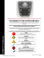
                        NOTE: CarShow System is only compatible with vehicles equipped with Single-Disc SYNC systems 


NOTICE OF INTENDED INSTALLATION AND USE


THE AUXILIARY VIDEO DISPLAY IS DISABLED WHEN THE VEHICLE

’S PARKING BRAKE IS NOT 

ENGAGED 


THE INSTALLER OF THIS PRODUCT MUST INSURE THE VIDEO DISABLE CONNECTION IS 

WORKING PROPERLY PRIOR TO DELIVERY OF THE VEHICLE.   


IMPROPER INSTALLATION COULD DISTRACT THE DRIVER OR INTERFERE WITH SAFE OPERATION 

OF THE VEHICLE, WHICH COULD RESULT IN SERIOUS INJURY OR DEATH, AND COULD ALSO 

VIOLATE STATE AND/OR FEDERAL LAW.  


CARSHOW ELECTRONICS DISCLAIMS ANY LIABILITY FOR ANY BODILY INJURY OR PROPERTY 

DAMAGE THAT MAY RESULT FROM ANY IMPROPER OR UNINTENDED INSTALLATION AND/OR USE. 
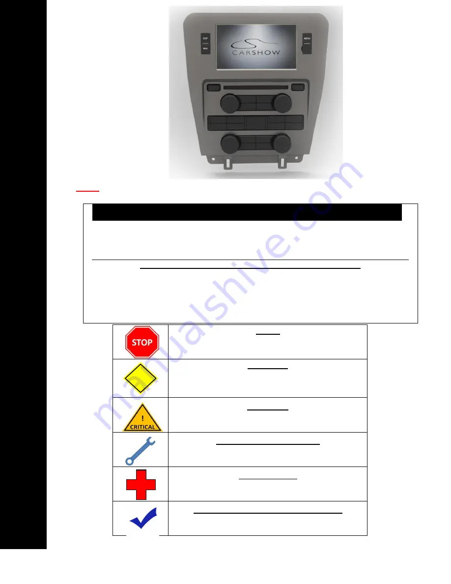


STOP 

Damage to the vehicle may occur 

Do not proceed until process has been completed 


CAUTION


CAUTION 

Process must be carefully observed in order to 

reduce the risk of damage to the accessory or 

vehicle


CRITICAL 

Process must be carefully observed in order to 

ensure a quality installation


TOOLS and EQUIPMENT 

Specific tools and equipment recommended for this 

process


SAFETY RISK 

Observe safe practices, this process can be 

dangerous and there is a risk of personal injury


TESTING and TROUBLESHOOTING 

Content specific testing and troubleshooting points  
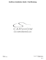


CS

-M

UST10 

Ford M

us

ta

n


Summary of Contents for CS-MUST10 Ford Mustang

Page 1: ...JURY OR DEATH AND COULD ALSO VIOLATE STATE AND OR FEDERAL LAW CARSHOW ELECTRONICS DISCLAIMS ANY LIABILITY FOR ANY BODILY INJURY OR PROPERTY DAMAGE THAT MAY RESULT FROM ANY IMPROPER OR UNINTENDED INSTALLATION AND OR USE STOP Damage to the vehicle may occur Do not proceed until process has been completed CAUTION CAUTION Process must be carefully observed in order to reduce the risk of damage to the ...

Page 2: ...um of 12 8 VDC This only takes seconds and can save hours of troubleshooting later TURN THE VEHICLE OFF Keep the Vehicle Off during the installation to avoid setting various Vehicle Fault sensors Keep the Vehicle OFF during the installation Failure to follow this may cause the AIRBAG FAULT SENSOR to become enabled Dealer Service Departments charge a significant fee to reset the Fault Sensor Discon...

Page 3: ...with panel pry tool CAUTION Remove Center Console Carefully remove back of center console with panel pry tool and pull straight up as shown at right Be sure to disconnect all harnesses CAUTION REMOVE THE FACTORY RADIO SYNC DISPLAY You will need to remove multiple interior trim components prior to removing the factory radio The following steps will help guide you through this process STEP 3 OEM Rad...

Page 4: ... Mounting Bolts Remove 7mm bolt on beneath climate controls on left hand side Remove Radio Panel Use your panel pry tool to carefully remove radio dash panel starting with top Use extreme caution to not break plastic Remove Radio Panel Then carefully remove right hand side portion of radio panel Use extreme caution to not break plastic Unplug harness Carefully unplug data harness from back of radi...

Page 5: ...e unplug OEM SYNC display NOTE Harness is extremely short so use caution Unplug harness Carefully unplug data harness from back of Sync display Remove Right SYNC Display Bracket Carefully remove 2 x phillips screws from right hand side mounting bracket Remove Left SYNC Display Bracket Carefully remove 2 x phillips screws from left hand side mounting bracket Set SYNC display aside as it will be re ...

Page 6: ... AC module is EXTREMELY fragile Installer assumes all liability if AC module is damaged AC Module Removal Carefully un mount AC module by pulling up Unplug harness Use extreme caution Remove Radio Mounting Bolts Remove 4 x 7mm radio mounting bolts Remove OEM Radio Unit Carefully remove oem radio unit NOTE Harnesses are extremely short so use caution Unplug OEM Radio Unit Carefully unplug radio har...

Page 7: ...d to prepare the OEM SYNC display to put back into dash The following steps will help guide you through this process STEP 4 Locate Included Foam Piece Foam piece for OEM SYNC display is shown at right Cut Adhesive Backing Cut of adhesive backing at top and bottom as shown at right DO NOT cut any more than of adhesive backing Place SYNC Display On Foam Place display onto foam and be sure that it is...

Page 8: ...gether as shown LOCATING REMOTE COMPONENTS You will need to mount the GPS Antenna on the exterior of the vehicle The following steps will help guide you through this process STEP 5 Use Caution around SRS Components It is the installer s responsibility to ensure that the safety equipment in the vehicle is NOT adversely affected by installation of this system Ensure that the routing of the harnesses...

Page 9: ...OEM and Rosen Bezel Preparation OEM Radio Bezel on right OE OEM Radio Face Assembly Remove 15 x T10 torx screws to remove OEM Radio face Assembly Screw locations highlighted in Yellow at right Be sure to place screws in a safe place as they will need to be re installed OE OEM Radio Control Assembly Radio Control assembly shown removed from Bezel at right OE OEM Radio Bezel Clips Remove plastic yel...

Page 10: ...ted They are left empty CarShow Radio Assembly Completed CarShow radio assembly at right INSTALL THE CARSHOW NAVIGATION SYSTEM You will need to prepare the CarShow Navigation System for installation in the vehicle STEP 7 Prepare the Vehicle side harnesses for connection to the CarShow Harness Use care not to pinch or damage cables as this will cause performance issues failures CAUTION Connect GPS ...

Page 11: ...Use care not to pinch or damage cables as this will cause performance issues failures Re install OEM Display AC Module Re install SYNC display OEM AC module in dash cavity above OEM radio Connect OEM SYNC Display to OEM harness that goes to OEM AC Module NOTE Be sure the harness is connected properly as SYNC system will not function properly unless connected Connect the Power Harnesses Be sure har...

Page 12: ...vehicle on and verify system powers up ENABLE INSTALLER SETTINGS You will need to select certain settings based on any Optional Equipment that you may have installed STEP 9 Launch the Setting Screen From the AM FM screen select Settings in the upper left hand corner Select the individual Settings as needed for the installed components Selectable options vary by product and installation Select the ...

Page 13: ... the unit starts up properly Troubleshooting 1 Reset the System while the Vehicle is ON 2 Confirm all connectors are properly installed 3 Check the Vehicle and System Fuses Select RADIO as the Source Select SATELLITE RADIO as the Source Select Phone as the Source Select NAV as the Source Confirm the Navigation loads and signal strength is OK Troubleshooting 1 Confirm the antenna has an unobstructe...

Page 14: ...nstallation Guide CS MUST IG Rev A Page 14 Select Reverse Camera Confirm the backup camera screen shows in reverse Troubleshooting 1 Confirm the Camera is set to ON in the Installer Settings 2 Confirm the Camera is receiving 12VDC as required Main Harness Diagram Option Harness Diagram ...

Page 15: ...CarShow Installation Guide Ford Mustang CarShow Copyright 2013 All Rights Reserved Installation Guide CS MUST IG Rev A Page 15 ...

Reviews: