background image

FOR TEC HNICAL SUPPOR T CALL 

1800 658 111

6

DC-1200P

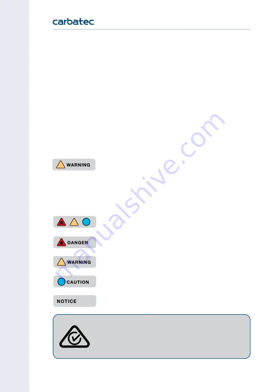
A safety alert symbol Indicates 

DANGER, WARNING

, or 

CAUTION. 

May be used in conjunction with other symbols or pictographs.

Indicates an imminently hazardous situation, which, if not avoided,  
will result in death or serious injury.

Indicates a potentially hazardous situation, which, if not avoided, 
could result in death or serious injury.

Indicates a potentially hazardous situation, which, if not avoided, 
could result in minor or moderate injury.

(Without Safety Alert Symbol) Indicates a situation that may result  
in property damage.

Carbatec products bearing the Regulatory Compliance Mark (RCM) have been 
tested in accordance with applicable Australian/New Zealand Standards 
to ensure their compliance with all mandatory standards and regulations 
(applicable at time of original sale). Carbatec Pty Ltd are registered as a 
responsible supplier with relevant Australian government departments and 
our products are registered on the EESS & ACMA database.

!

!

!

!

SYMBOL MEANING

IMPORTANT!

 Safety is the single most important consideration in the operation of this 

equipment. The following instructions must be followed at all times. Failure to follow all 

instructions listed below may result in electric shock, fire, and/or serious personal injury. 


There are certain applications for which this tool was designed. We strongly recommend 

that this tool not be modified and/or used for any other application other than that for 

which it was designed. If you have any questions about its application, do not use the tool 
until you have contacted us and we have advised you.
The purpose of safety symbols is to attract your attention to possible dangers. The safety 
symbols and the explanations with them deserve your careful attention and understanding.  
The symbol warnings do not, by themselves, eliminate any danger. The instructions and 
warnings they give are no substitutes for proper accident prevention measures.

!

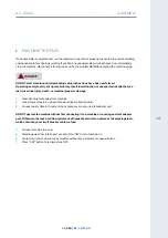
Be sure to read and understand all safety instructions in this manual, including all safety  
alert symbols such as “DANGER,” “WARNING,” and “CAUTION” before using this tool. 

Failure to following all instructions listed below may result in electric shock, fire, and/or 

serious personal injury.

SAFETY INSTRUCTIONS

Summary of Contents for DC-1200P

Page 1: ...CARBATEC COM AU D C 1 2 0 0 P M A N U A L 2HP Dust Collector 2...

Page 2: ...and technological advancements more accessible to Aussie woodworkers Backed by our no fuss after sales care and warranty support you can trust Carbatec to keep you woodworking as promised We look for...

Page 3: ...protective coatings can be removed by spraying WD 40 on them and wiping it off with a soft cloth This may need to be redone several times before all of the protective coatings are removed completely 3...

Page 4: ...erial number and date of purchase in your manual for future reference 2 Made in for CARBATEC PTY LTD Brisbane Australia Model Voltage Freq Phase Amp kW Speed Lot No Serial No Date QUALITY INSPECTED Ke...

Page 5: ...re has been taken to ensure that the information in this manual is correct to provide you with the guidelines for the proper safety assembly and operation of this machine Introduction 2 What s in the...

Page 6: ...afety is the single most important consideration in the operation of this equipment The following instructions must be followed at all times Failure to follow all instructions listed below may result...

Page 7: ...s intended applications 3 GROUND ALL TOOLS If the tool is supplied with a 3 prong plug it must be plugged into a 3 contact electrical receptacle The third prong is used to ground the tool and provide...

Page 8: ...NOT STORE ANYTHING ABOVE OR NEAR the tool where anyone might try to stand on the tool to reach it 19 MAINTAIN YOUR BALANCE Do not extend yourself over the tool Wear oil resistant rubber soled shoes K...

Page 9: ...ons NEVER use an extension cord rated at less than your machine Longer run extensions will need heavier duty extension cords Only connect your extension cord or machine to a receptacle that accepts yo...

Page 10: ...ne with respect and caution to lessen the possibility of operator injury If normal safety precautions are overlooked or ignored serious personal injury may occur DUST COLLECTOR SAFETY EMPTYING DUST Wh...

Page 11: ...ion with or without yellow stripes is the equipment grounding conductor DO NOT connect the equipment grounding conductor to a live terminal if repair or replacement of the electric cord or plug is nec...

Page 12: ...er bag support rod not shown B Filtration bag C Impellor to collector hose D Collection bag E Collector support rods F Base G Swivel casters x 4 H Collector I ON OFF switch J Motor K Inlet port DC 120...

Page 13: ...ECTION BAG TYPE Plastic DRUM DIAMETER 480 mm FILER BAG FITTED Needlefelt 5 micron INLET HOLE SIZE 1 x 125 2 x 100 mm NUMBER OF INTAKE HOLES 2 x 100 mm BAG VOLUME 0 15m3 AIR FLOW MAX 1200CFM OVERALL SI...

Page 14: ...rier and or shipper must be notified of this fact immediately to establish any claim which might arise A PLACEMENT LOCATION Consider anticipated workpiece sizes and additional space needed for auxilia...

Page 15: ...hly first clean any parts that are covered or coated in heavy duty rust preventative if applicable B ATTACHING CASTERS 1 To assemble place the base plate upside down and attach the four casters throug...

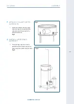
Page 16: ...t mount the outlet adaptor I to the collector body as shown with seal seated between housing and fitting Fig D1 D2 E MOUNTING SUPPORT TO BASE 2 The collector supports can now be mounted to the base pl...

Page 17: ...tor to the two outer collector supports ensuring that the collector hole is facing towards the impellor motor assy Fig F G INSTALL UPPER BAG SUPPORT 1 The upper bag support can now be installed onto t...

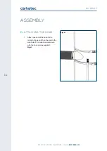
Page 18: ...RT CALL 1800 658 111 18 DC 1200P ASSEMBLY H ATTACHING THE HOSE 1 Attach one end of the hose to the collector body and the other end to the side hole of the collector and secure with the hose clamps su...

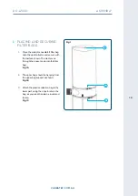
Page 19: ...the dust collector and secure with the belts as shown The clamp runs through the pocket sewn into the filter bag Fig IA 2 The upper bag should be hanging from the upper bag support as shown Fig IB 3...

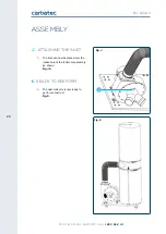
Page 20: ...111 20 DC 1200P Fig K ASSEMBLY J ATTACHING THE INLET 1 The inlet can now be placed over the intake hole of the fan motor assembly as shown Fig JA K READY TO PERFORM 2 The dust collector is now ready...

Page 21: ...that can lead to serious injury death or machine property damage 1 Clear all setup tools away from machine 2 Lock all swivel casters on base stand and dust collection drum 3 Connect dust collector to...

Page 22: ...al Carbatec store for more information OPERATION M OPERATION The purpose of this overview is to provide the novice machine operator with a basic understanding of how the machine is used during operati...

Page 23: ...rated CFM extraction requirement available Please note that CFM requirement is usually measured at the point where the dust hose is connected to the machine s dust port which is very different to the...

Page 24: ...nance schedule must be strictly followed ongoing If you ever observe any of the below shut down the machine immediately and fix the problem before continuing operations Loose mounting bolts Damaged fi...

Page 25: ...nts into collection bag and inspect for damage Replacement collection bags for your dust collector are available from Carbatec S EMPTYING YOUR COLLECTION BAG 1 Wear a respirator and safety glasses and...

Page 26: ...FOR TECHNICAL SUPPORT CALL 1800 658 111 26 DC 1200P 2HP Dust Collector DC 1200P PARTS DIAGRAM...

Page 27: ...LECTOR 1 9 SWITCH 1 34 BAG CLAMP 2 11 WRENCH HEX 1 35 FILTER BAG 1 13 UPPER BAG SUPPORT 1 36 COLLECTOR BAG 1 15 SCREW HEX 6 37 COLLECTOR SUPPORT 3 16 WASHER 28 41 SCREW HEX 4 17 KEY 1 42 FAN HOUSING 1...

Page 28: ...ds close other branches 3 Canister filter clogged or at fault Clean canister filter Replace canister filter 4 Dust extractor too far from machine or undersized for dust extraction system Move closer t...

Page 29: ...nch lines at one time causing velocity drop in main line Open 1 or 2 more blast gates to different branch lines to increase main line velocity 8 Ducting and ports are incorrectly sized Install correct...

Page 30: ...FOR TECHNICAL SUPPORT CALL 1800 658 111 30 DC 1200P WIRING DIAGRAM BROWN BLUE YELLOW GREEN OVERLOAD 9A RED BROWN BLUE MOTOR 230V 50HZ 500W KJD12 YELLOW GREEN L N PE FR M 1 2 3 4...

Page 31: ...in the email the following information 1 a copy of the order or receipt for the goods 2 the serial or batch number printed on the machinery manufacturing plate and 3 a detailed description of the faul...

Page 32: ...2 CARBATEC COM AU Carbatec Pty Ltd E info carbatec com au AU 1800 658 111 NZ 0800 444 329 128 Ingleston Road Wakerley Queensland Australia 4154 ABN 84 010 706 242...

Reviews: