


7
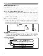
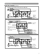
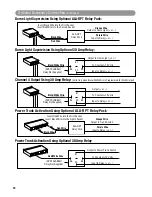
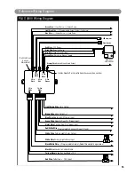
5 Wire Ground at Rest Door Locking Systems
87
87A
85
86
30
87
87A
85
86
30
To +12 Volts
(B)
To Power
Lock Switch
To Power
Lock Motors
White Wire: Lock
Brown Wire: Unlock
Green Wire: Lock
Blue Wire: Unlock
Violet Wire
ALA-DL1
Relay Pack
Red Wire: Lock
Black Wire: Unlock
Black 3-Pin
Connector
Green Wire
Blue Wire
Note 1: Orange wire (Not Shown)
from ALA-DL1must be connected
to +12V
Note 2: For bulk relay usage, wiring
shown still applies
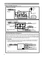
Black 3-Pin Connector
(Continued)
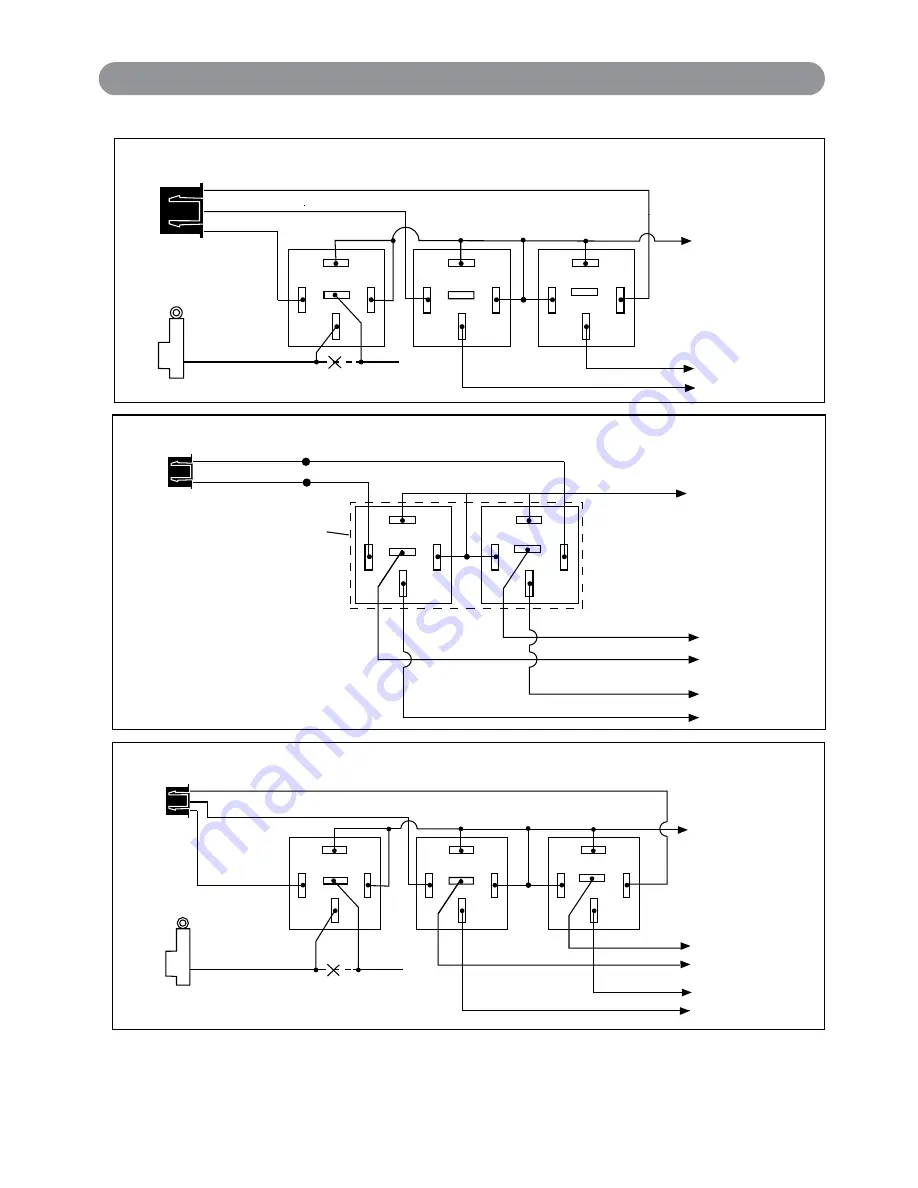
Unlock Driver's Door First Wiring for 3-Wire Positive Door Locking Systems
87
87A
85
86
30
87
87A
85
86
30
To +12 Volts
(B)
To Power
Door Lock
Switch
Lock/Unlock
Wires
Lock
Unlock
87
87A
85
86
30
+ Unlock
Cut
Driver's
Door
Motor
Blue Wire
Green Wire
Light Blue Wire
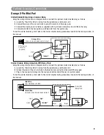
Unlock Driver's Door First Wiring for 5-Wire Ground at Rest Door Locking Systems
87
87A
85
86
30
87
87A
85
86
30
To +12 Volts
(B)
To Power
Lock Switch
To Power
Lock Motors
Lock
Lock
Unlock
Unlock
87
87A
85
86
30
+ Unlock
Cut
Driver's
Door Motor
Green Wire
Blue Wire
Light Blue Wire
Wiring
(Continued)
PLUS-4900-IM.qxp 4/30/09 3:06 PM Page 7


