background image


B-3                                OPERATION                                      B-3 

CONTROLS AND SETTINGS   

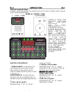
All operator controls and adjustments are located on the case front of the TIG machine. Refer to Figure B.1 
and the corresponding explanations.   

FIGURE B.1 CONTROL PANEL 

1.  FRONT  PANEL               2. BACK PANEL       


1.indication of welding current 


2.power switch    3.pulse current 
regulator   4.AMP regulator 


5.Pulse Ttime On                     
6.pulse 

Freq. 

regulator    

7.indicating light of power         
8. indicating light of over heat       
9. current up-slope time regulator 
10.current down-slope time 
regulator 11.post flow time 
regulator  12.MMA/TIG/CUT 


switch 13.AC balance14.output"+" 
15.AC square wave Frequency  

16.   arc force  17.argon out    
18.torch control  (or remote 
control) 19.  AC/DC TIG switch     
20.    output"-"  21.argon  inlet     
22.power supply  23.nameplate   
24.fan 25.safety earthing column   
26.  2  steps/ 4 steps switch  
27. 220v  receptacle 
28,PreFlow29.Start Amps 
30.End Amps 31.Pulse On/Off. 
32.warning indicating light     
34.Pilotarc 


CONTROL FUNCTIONALITY   


 1 DIGITAL METER

 -

 A 3 digit LED meter is 

used to display the preset output current level 
before welding, and actual output level while 
welding: A lit display indicates input power is turned 
on. (See Item 2.) 

2.POWER SWITCH

 - 

Input line switch turns 

input power ON or OFF, as indicated by the on or 
off status of the front panel digital display (See Item 
1).  

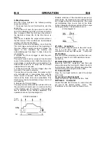
3. Pulse current regulator


Regulating the knob, It  can  be  selected 

between 5A TO 250A.   

4. welding current regulator 

Regulating the knob, It  can  be  selected 
between 5A TO 250A.


For Remote TIG this knob 

sets the Max.Amp level, with the Remote 

Adjustable foot control

 (if used). 

5.pulse width regulator   

Regulating the knob, It  can  be  selected 
between 0.1 TO 0.9.


6.pulse Freq. regulator   

Regulating the knob, It  can  be  selected 
between 0.5Hz TO 250Hz.


Summary of Contents for PowerMaster256

Page 1: ...200 Amp de MMA en monofásico 220V con un ciclo de trabajo del 60 en TIG y 35 en MMA La unidad está equipada con frecuencia de AC control de balance de AC con función de corte con plasma de 60 A que corta hasta 22 mm de espesor en acero al carbón con inicio de arco blow back y arco piloto El módulo inversor IGBT reduce el tamaño La unidad cuenta con capacidad de arranque de bajo amperaje en AC o DC...

Page 2: ...4IN1 MACHINE Suitable for 1x220V Operators s Manual Safety Setup and General Use Guide REV 2 0 00147 16 Issue Date May 19 2016 Manual No 0 1537 EMPRESAS CARBONE S A Calle 5ta Rio Abajo Panamá Panamá Telefonos 507 3916309 3916313 www empresascarbone com ...

Page 3: ...performance Should you have an issue or question concerning your unit please contact performance technical support available through the main company headquarters available in your country For best service call the appropriate support line and follow up with an email particularly if off hours or you cannot reach a live person In the event you do not reach a live person particularly during heavy ca...

Page 4: ..._________ Where Purchased _____________________________ Whenever you request replacement parts or information on this equipment please always supply information you have recorded above This product is covered by 1 years parts and labour warranty you are responsible for costs of shipping unit to us we will cover cost of returning item to you External items torch earth lead etc are covered by 3 mont...

Page 5: ...re information please contact our Support The warranty does not cover improper use maintenance or consumables Do not attempt to alter or defeat any piece or part of your unit particularly any safety device Keep all shields and covers in place during unit operation should an unlikely failure of internal components result in the possible presence of sparks and explosions If a failure occurs disconti...

Page 6: ...otection is available exclude them from the work area Even brief expo sure to the rays from the welding arc can damage unprotected eyes Always wear hearing protection because welding and cutting can be extremely noisy E ar protection is necessary to prevent hearing loss Even prolonged low levels of noise has been known to create long term hearing damage Hearing protection also further protects aga...

Page 7: ...es nose or throat are signs that you need to increase ventilation Stop immediately and relocate work if necessary until adequate ventilation is ob tained Stop work completely and seek medical help if irritation and discomfort persists WARNING Do not weld on galvanized steel stainless steel beryllium titanium cop per cadmium lead or zinc without proper respiratory equipment and or ventilation WARNI...

Page 8: ... materials including rags and spare clothing away from area Keep all flammable fuels and liquids stored separately from work area Visually inspect work area when job is completed for the slightest traces of smoke or embers If welding or cutting outside make sure you are in a cleared off area free from dry tender and debris that might start a forest or grass fire Do not weld on tanks drums or barre...

Page 9: ...imitations B 2 Control Panel B 3 Controls and Settings 2 Step and 4 Step Tig Sequence B 3 B 6 Operating steps B 7 Welding in Tig mode B 7 Welding Polarity B 7 DC Electrode Negative Polarity B 7 DC Electrode Positive Polarity B 7 D C Pulsed TIG B 7 A C Alternating Current B 8 A C Pulsed TIG Alternating Current Pulsed B 8 Steel Tig Welding B 8 Copper Tig Welding B 8 Tips For AC TIG Welding B 8 GTAW ...

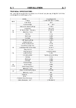
Page 10: ...s 5 250A AC TIG End Amps 5 250A AMP Adjusting Range 5 250A Rated Duty Cycle 60 Current Up slope Time 0 10S Current Down slope Time 0 25S pulse Base AMP Current Ratio 5 95 Pluse Time On 0 1 0 9 Pluse Frequency 0 5 25 25 250 Hz post Flow Time 0 25s Arc starting Mode high frequency arc striking Pre Flow 0 10s Start Amps 5 250A DC TIG End Amps 5 250A No load Voltage 70V Current Range 5 200A Rated Outp...

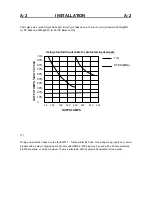
Page 11: ... 1 National Electric Code Use a Super Lag type fuse or circuit breaker with a delay in tripping action Models with NEMA 6 50P plug may be used with a 50 amp protected 6 50R receptacle or with a maximum 70 amp protected 6 50R receptacle if dedicated for the welder 120 140 160 180 200 220 240 260 100 90 80 70 60 50 40 30 20 10 0 OUTPUT AMPS OUTPUT AMPS DUTY CYCLE Using standard input cable for prote...

Page 12: ...t of the equipment Never make the cargo pass or leave it suspended over people or things Neither let the equipment or the single unit fall nor put it down with force Once it has been removed from the packing the power source can be used to move it in the hand or on the shoulder Never lift welder with gas cylinder attached Never lift welder above personnel TILTING Each machine must be placed on a s...

Page 13: ... to an earth ground close to the work clamp using one of the following methods a A metal underground water pipe in direct contact with the earth for ten feet or more b A 3 4 19mm galvanized pipe or a 5 8 16mm solid galvanized iron steel or copper rod driven at least eight feet into the ground The ground should be securely made and the grounding cable should be as short as possible using cable of t...

Page 14: ... or defeat the purpose of the power cord ground pin RECONNECT PROCEDURE The Inverter machine auto reconnects to either 115V or 230V supply Fuse the input circuit with time delay fuses or delay type1 circuit breakers Using fuses or circuit breakers smaller than recommended may result in nuisance shut offs from welder inrush currents even if not welding at high currents The Inverter machine is recom...

Page 15: ...per procedure on grounding the work clamp and work piece SHIELDING GAS CONNECTION Obtain the necessary inert shielding gas usually argon Connect the cylinder of gas with the pressure regulator and flow gage Install the gas hose between the regulator and gas inlet located on the rear of the welder CYLINDER could explode if damaged Keep cylinder upright and chained to a support Keep cylinder away fr...

Page 16: ...nder electrically hazardous conditions such as welding in wet areas or on or in the workpiece FUMES AND GASES can be dangerous Keep your head out of fumes Use ventilation or exhaust at the arc or both to remove fumes and gases from breathing zone and general area WELDING SPARKS can cause fire or explosion Keep flammable material away Do not weld on containers that have held combustibles RC RAYS ca...

Page 17: ...ell as many industry standard items such as TIG torches adapted for Twist Mate hoses PROCESS LIMITATIONS The Precision TIG machines are not recommended for arc gouging due to it s limited output capacity and are also not recommended for pipe thawing RECOMMENDED QUIPMENT INTERFACE See Installed Options in Accessories Section for more details The Precision TIG will be available as a basic Machine On...

Page 18: ...arthing column 26 2 steps 4 steps switch 27 220v receptacle 28 PreFlow29 Start Amps 30 End Amps 31 Pulse On Off 32 warning indicating light 34 Pilotarc CONTROL FUNCTIONALITY 1 DIGITAL METER A 3 digit LED meter is used to display the preset output current level before welding and actual output level while welding A lit display indicates input power is turned on See Item 2 2 POWER SWITCH Input line ...

Page 19: ...egative wave at full CW rotation setting to Max Cleaning 70 positive wave at CCW rotation This setting position feature automatically provides the proper amount of cleaning and penetration for normal AC TIG welding 14 output Electrode Connection Positive For quick disconnect system using Twist Mate cable plugs 15 AC square wave Frequency Regulating the knob It can be selected between 20 TO 250Hz 1...

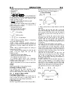
Page 20: ...tep mode which is selected with the Trigger Mode Push Button 2 Step Sequence With the Trigger Mode switch in the 2 step position the following welding sequence will occur This sequence is shown in 2 step diagram 1 2 STEP DIAGRAM 1 1 Press and hold the Arc Start Switch to start the sequence The machine will open the gas valve to start the flow of the shielding gas After a 0 5 second preflow time to...

Page 21: ...This Finish current can be maintained as long or as short as necessary 4 Release the TIG torch trigger The output current of the machine will turn OFF and the gas valve will remain open to continue the flow of the shielding gas The duration of this postflow time is adjusted by the Postflow parameter This operation is shown in 4 step diagram 1 4 STEP DIAGRAM 1 Possible variations of this standard s...

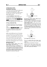
Page 22: ...urn on with the output and remain on continuously until the remote control is released WELDING POLARITY DC Electrode Negative Polarity Direct Current Straight Polarity see FIGURE B 4 While Welding there is a continuous flow of electrons from the electrode to the workpiece This is the most used polarity ensuring limited wear of the electrode since the majority of the heat concentrates on the anode ...

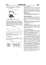
Page 23: ...e gas Considering the fluidity of molten copper the use of backup support may prove useful FILLER MATERIAL In order to avoid the oxidation of the molten material filler materials containing phosphorus silicon or other deoxidating materials are typically used The mechanical properties can also be improved through the use of silver TIPS FOR AC TIG WELDING AC Inverter TIG power sources offer two sign...

Page 24: ... 2 4 Up to MAX A Up to 160 A Up to MAX A 13 17 6 8 11 15 5 7 1 8 3 2 X Up to MAX A X 15 23 7 11 11 15 5 7 Tungsten electrodes are classified as follows by the American Welding Society AWS Pure EWP green 1 Thoria EWTh 1 yellow 2 Thoria EWTh 2 red 2 Ceria EWCE 2 orange 1 5 Lanthana EWLa 1 black 0 5 to 0 40 Zirconia EWZr brown TRI MIX of elements EWG gray Ceriated Tungsten is now widely accepted as a...

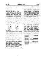
Page 25: ...laces a lot of heat on the tungsten In a balanced wave where both EP and EN are equal in time length 50 penetration is reduced and over cleaning results in wide etch lines running parallel to the side of the weld Not all welds conditions will be alike so more cleaning is required at times than others Similarly more penetration will be required at times than others Ordinarily about 30 35 electrode ...

Page 26: ...ll and service this equipment Turn the input power off at the fuse box disconnect or unplug supply lines and allow machine to sit for five minutes minimum to allow the power capacitors to discharge before working inside this equipment Do not touch electrically hot parts Connect up the shielding gas typically argon using an appropriate regulator Connect Adjustable foot control torch and work lead t...

Page 27: ...rator may have to turn the cur rent control up and depress the Ampcontrol approximately 1 4 of the way down Depressing the Ampcontrol to its minimum position may not start the arc Also if the current control is set too low the arc may not start In most cases a large or cold tungsten will not readily establish an arc at low currents This is normal In Direct Current mode the PRECISION TIG will start...

Page 28: ...B 13 OPERATION B 13 ...

Page 29: ...B 14 OPERATION B 14 ...

Page 30: ...B 15 OPERATION B 15 ...

Page 31: ...ever the power switch is turned on 5 Turn the power switch to ON 6 Adjust the Current Control to the desired amps 7 Strike an arc and weld NOTE When the MMA TIG CUT switch is set to MMA the output is always on when the power switch is on A remote control has no effect on the welding current and the gas flow and high frequency TIG arc starter are disabled RECOMMENDED ELECTRODE AMPERAGE RANGES SMAW ...

Page 32: ...and automatic amp response needed to maintain the arc when voltage falls below the threshold 6011 Cellulose electrodes may require more arc force control than other rods but each brand and size will weld a little differently The arc force control setting will vary from person to person as well with different rod angles positions and arc lengths all factoring into the arc force control performance ...

Page 33: ...nt air pressure If pressure is too low the unit will cease output and the green indicator light next to the pressure gauge will go out to indicate the air pressure is too low to operate safely 4 See torch manual included in this manual for best pressure settings and parts identification 5 Do not exceed 90 psi air supply pressure from compressor or failure or leakage of internal line components may...

Page 34: ...B 19 OPERATION B 19 ...

Page 35: ...B 20 OPERATION B 20 ...

Page 36: ...B 21 OPERATION B 21 ...

Page 37: ...B 22 OPERATION B 22 ...

Page 38: ...equire no maintenance 7 SPARK GAP ADJUSTMENT The spark gap 020 5mm is set at the factory to a gap of 0 015 inches 0 4mm See Figure D 1 This setting is adequate for most applications Where less high frequency is desired the setting can be reduced to 0 015 inches 0 4mm Use extreme caution when working with circuit of the high frequency The high voltages developed can be lethal Turn the input power o...

Page 39: ...S This column describes possible symptoms that the machine may exhibit Find the listing that best describes the symptom that the machine is exhibiting Step 2 POSSIBLE CAUSE The second column labeled POSSIBLE CAUSE lists the obvious external possibilities that may contribute to the machine symptom Step 3 RECOMMENDED COURSE OF ACTION This column provides a course of action for the Possible Cause gen...

Page 40: ... unit to run until the fan cools the unit and the yellow light goes out Machine does not respond no gas flow no high frequency and no open circuit voltage when arc start switch or Ampcontrol is activated fan is working 1 Machine MUST be in the TIG Mode 2 The Ampcontrol may be defective Check for continuity between pins D and E on cable connector when Ampcontrol is depressed Welding stops and warni...

Page 41: ...significantly when AC Balance control knob is set near or at max penetration or when Output control is set near or at full output 1 Input power to machine doesn t have sufficient capacity Try changing Input power to a sufficient supply refer to Installation section 2 Machine is powered from an engine generator or an engine welder If welding at high currents are needed try powering machine from ele...

Page 42: ...g 2 Tungsten not sharp when welding in DC mode 3 Gas shielding may be insufficient Increase gas flow reduce tungsten stick out beyond gas cup 4 Check for contaminated gas or leaks in the gas line torch or connections 5 If a helium blend is used as a shielding gas then reduce the percentage of helium Arc Pulsates when AC TIG welding 1 Micro Switch mounted on Polarity Switch is not opening in AC mod...

Page 43: ...ck Spark Gap operation and setting 0 5mm High frequency spark is present at tungsten electrode but operator is unable to establish a welding arc Machine has normal open circuit voltage refer to Technical Specifications in the Installation Chapter 1 The tungsten electrode may be contaminated Replace or sharpen 2 The current control may be set too low 3 The tungsten electrode may be too large for th...

Page 44: ...t your local welder gas distributor When AC TIG welding the arc is erratic and there is a loss of cleaning of the work piece 1 Tungsten electrode may be too small for process Use a larger diameter tungsten or a pure tungsten 2 If a helium blend is used as a shielding gas then reduce the percentage of helium If all recommended possible areas of misadjustment have been checked and the problem persis...

Page 45: ...ler diameter electrode 2 Arc too short Excessive spatter 1 Long arc 2 High current Craters 1 Fast movement of the electrode away from piece Inclusions 1 Poor cleanliness or distribution of the Welding passes 2 Improper movement of the electrode Insufficient penetration 1 High progression speed 2 Welding current too low 3 Narrow chamfering Porosity 1 Humidity in electrode 2 Long arc If all recommen...

Page 46: ...E 1 NOTE This diagram is for reference only It may not be accurate for all machines covered by this manual If the diagram is illegible write to the Service Department for a replacement Give the equipment code number ...

Page 47: ... Adjustable foot control 1 Cutting torch 1 Electrode 5 Tip 1 0 5 Ceramic shieid 3 Operation instructions 1 Certificate of quality 1 No Certificate of quality Name of product AC DC TIG DC STICK DC CUT WELDING Type of product PowerMaster 256 Packing No Test results of this welder fulfils_____________ _________technical requirements and its release from the works is granted Inspector_________ Date___...

Page 48: ...electrically live parts or electrode with skin or wet clothing Insulate yourself from work and ground No toque las partes o los electrodos bajo carga con la piel o ropa moja da Aislese del trabajo y de la tierra Ne laissez ni la peau ni des vête ments mouillés entrer en contact avec des pièces sous tension Isolez vous du travail et de la terre Berühren Sie keine stromführenden Teile oder Elektrode...

Page 49: ...gute Be und Entlüftung des Arbeitsplatzes Mantenha seu rosto da fumaça Use ventilação e exhaustão para remover fumo da zona respiratória Turn power off before servicing Desconectar el cable de ali mentación de poder de la máquina antes de iniciar cualquier servicio Débranchez le courant avant l entre tien Strom vor Wartungsarbeiten abschalten Netzstrom völlig öff nen Maschine anhalten Não opere co...

Reviews: