background image


_________________________________________________________________________________________________________________________ 
Card Access Sensor Bridge 


      Page 4 of 12 

Quick Start & Installation Guide 


Card Access, Inc.


Tools and Supplies Needed 


To complete the installation, you will need the following tools and supplies:


Screwdrivers 


Drill with bits 


Mounting screws and anchors (included)  


Mounting 

The bridge can be mounted on any interior wall (protected from the elements) by following these steps:  

1. 

Remove the cover retaining screw from the bottom of the bridge. 

2. 

Insert a screwdriver between the cover and the screw mount, and then pry to remove the bridge cover. 

3. 

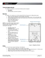
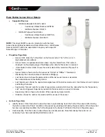
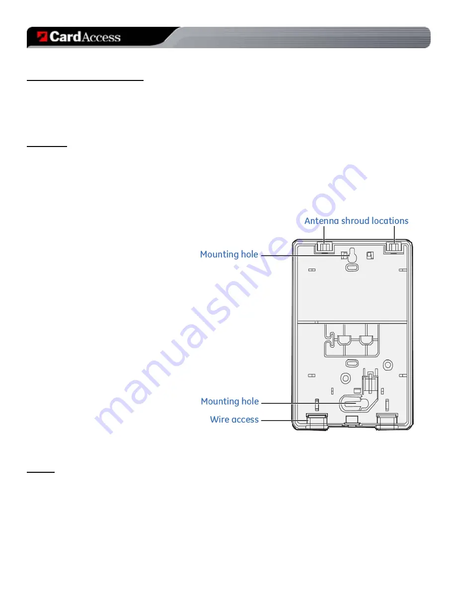
Hold the bridge (without cover) against the mounting surface and mark the two mounting holes and the 
wire access hole as shown in 

Figure 2

. Remember to leave at 

least 10 in. (25 cm) above the 
bridge for the antennas. 


NOTE:

 The circuit board may be hinged out of the 

bridge base plastics to gain better access to the 
mounting holes by pulling downward on the 
retaining latch with a finger. 


4. 

Drill holes and insert the 
appropriate anchors. 

5. 

Use the wire access hole to route 
the wires from the DC power 
supply (included) into the bridge 
base.  

6. 

Secure the bridge base to the 
wall with the pan head screws 
provided. 

7. 

To assemble the antenna 
shrouds, attach the proper 
number of sections (3) together, 
then attach the top cap. 

8. 

Straighten the wire antennas so 
that they extend straight upward 
from the bridge. Then slide each 
antenna shroud over the antenna 
and snap it into the bridge base 
plastics. 


Figure 2 – Bridge Base Plastics 

Wiring 

To wire the DC power supply to the bridge, do the following: 

1.  Remove AC power (if applied) to the included DC power supply. 
2.  Wire the white-striped conductor from the power supply to the bridge terminal marked ‘+12’. Wire the solid 

black wire (no stripe) to the bridge terminal marked ‘GND’. See 

Figure 3

.  

3.  Replace Bridge cover and secure with cover retaining screw. 

Do not over-tighten.


Summary of Contents for ZGB10A

Page 1: ...______________________________________________________________________________ Card Access Sensor Bridge Page 1 of 12 Quick Start Installation Guide Card Access Inc Sensor Bridge Model Numbers ZGB10A ZGB10A ZP Quick Start and Installation Guide ...

Page 2: ...______________________________________________________________________________________________________________________ Card Access Sensor Bridge Page 2 of 12 Quick Start Installation Guide Card Access Inc ...

Page 3: ...device gives the homeowner the ability to utilize the wide range of GE sensors available as accessories to the Control4 system The device consists of a self contained wall mountable bridge in a plastic enclosure It is powered by a 12V DC adapter Specifications ZGB10A Specifications Dimensions 4 6 x 14 4 x 1 5 117mm x 366mm x 38mm Weight 0 5 Lbs 0 23Kg Maximum Ambient Operational Temperature 140 F ...

Page 4: ... circuit board may be hinged out of the bridge base plastics to gain better access to the mounting holes by pulling downward on the retaining latch with a finger 4 Drill holes and insert the appropriate anchors 5 Use the wire access hole to route the wires from the DC power supply included into the bridge base 6 Secure the bridge base to the wall with the pan head screws provided 7 To assemble the...

Page 5: ...tton at the top of the screen 3 When prompted to identify the unit press the ID button on the Bridge by using a paper clip inserted through the small hole located on the face of the Bridge Press the button four times in succession The BUS LED on the Sensor Bridge will begin blinking as it attempts to join the ZigBee mesh and identify into the Control4 project 4 When the Sensor Bridge has successfu...

Page 6: ...he wireless sensor Then click the Set button 4 Test the sensor by activating deactivating the sensor s input You will see the sensor status populate on the properties page as well as the wireless signal level of the sensor to bridge connection 5 Select the generic proxy of your choice and at it to your project Go to the Connections tab and under Control AV bind the output for the sensor to this pr...

Page 7: ...rivers provide a good deal of diagnostic information to assist in deployment of Sensor Bridges as well as placement and testing of wireless sensors The information below is also included in the Documentation tab of each driver ZGB10A Driver Details Supported Devices o First Card Access Sensor Bridge in a project Model Number ZGB10A Properties Page Help o Bridge Status Displayed as Online or Offlin...

Page 8: ...us and low battery status o Last Signal Level shows the approximate signal level of the last received event Use this level to aid in proper positioning of sensors o Supervisory Timeout sets the number of supervisory periods which must be missed before the Supervisory Lost event is triggered Supervisory periods for these sensors are every 64 minutes o Supervisory State shows current state of the su...

Page 9: ...or Status shows whether the sensor as Online or Offline This status is affected by the connection state of the Sensor Bridge s o Last Sensor Event shows the date and time of the last event received as well as the contact status and low battery status o Last Signal Level shows the approximate signal level of the last received event Use this level to aid in proper positioning of sensors o Supervisor...

Page 10: ...her the sensor as Online or Offline This status is affected by the connection state of the Sensor Bridge s o Last Sensor Event shows the date and time of the last event received as well as the contact status and low battery status o Last Signal Level shows the approximate signal level of the last received event Use this level to aid in proper positioning of sensors o Supervisory Timeout sets the n...

Page 11: ... ZGB10A to which this declaration relates are in conformity with the following standards and or other normative documents EN60950 EN55022 EN55024 We hereby declare that the above named product is in conformity with the essential requirements and other relevant provisions of Directive 1999 5 EC The conformity assessment procedure referred to in Article 10 3 and detailed in Annex II of Directive 199...

Page 12: ...cannot guarantee the accuracy of any information presented after the date of this document s publication COPYRIGHT 2009 Card Access Inc All rights reserved Any previously copyrighted contents contained herein remain the property of the respective creators Card Access The Wire Stops Here and Do More Control More Make More are trademarks of Card Access Inc Control4 is a registered trademark and 4Sig...

Reviews: