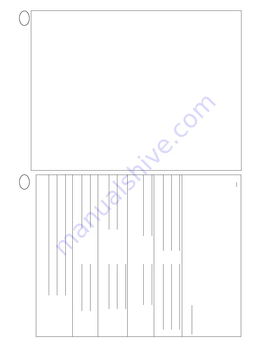
Inspection
and
test
log
book
for
the
door
system
T
esting
of
door
system
Owner
/
operator
of
the
system:
Location
of
door
system:
Operator
data:
Operator
type:
Manufacturer:
Date
of
manufacture:
Operating
mode:
Door
data:
T
ype:
Serial
no.:
Door
dimensions:
Y
ear
of
construction:
Leaf
weight:
Installation
and
initial
operation
Company
,
installer:
Initial
operation
on:
Name,
installer:
Signature:
Other
details
Subsequent
alterations
Retain
these
installation,
operating
and
maintenance
instructions
for
the
full
duration
of
the
operator
’s
service
life!
GB
Retain
these
installation,
operating
and
maintenance
instructions
for
the
full
duration
of
the
operator
’s
service
life!
GB
General
information
When
being
put
into
service
power-
operated
doors
must
be
inspected
and
maintained
by
correspondingly
qualified
persons
(persons
with
suitable
training
and
qualifications
based
on
knowledge
and
experience)
at
intervals
as
specified
in
the
manufacturer
's
maintenance
instructions
and,
if
necessary
,
also
in
accordance
with
any
special
national
regulations
(e.g.
BGR
232
"Guidelines
for
P
ower-operated
Windows,
Doors
and
Gates").
All
inspections
and
maintenance
carried
out
must
be
documented
in
the
inspection
log
book
provided.
It
must
be
kept
safe
by
the
owner-
operator
,
together
with
the
documentation
on
the
door
system,
throughout
the
operator's
entire
service
life
and
must
be
filled
out
in
full
and
handed
over
to
the
owner-
operator
by
the
installer
at
the
latest
at
the
time
of
putting
into
service.
(W
e
also
recommend
this
for
manually
operated
doors.)
It
is
absolutely
imperative
that
the
guidelines
provided
in
the
documentation
accompanying
the
door
system
(Installation,
Operating
and
Maintenance
Instructions
etc.)
are
adhered
to.
The
m
anufacturer's
guarantee
becomes
null
and
void
in
the
event
that
inspection
/
maintenance
has
not
been
properly
carried
out.
Alterations
to
the
door
system
(in
as
far
as
permitted)
must
also
be
documented.
Caution:
An
inspection
is
the
same
as
maintenance!
not
Check
list
of
door
system
(Document
the
equipment
present
at
the
time
of
initial
operation
by
ticking
off)
Equipment
present
Features
to
be
tested
applicable
Remark
1.0
Door
1.1
________________________
Manual
operation
of
the
door
Smooth
running
1.2
/
________________________
Fastenings
/
connections
State
Seat
1.3
/
________________________
Pivots
/
joints
State
Lubrication
1.4
/
________________________
T
rack
rollers
/
track
roller
holders
State
Lubrication
1.5
/
________________________
Seals
/
sliding
contact
strips
State
Seat
1.6
/
________________________
Door
frame
/
Door
guide
Alignment
Fastening
1.7
/
________________________
Door
leaf
Alignment
State
2.0
W
eight
counterbalance
/
safe
opening
2.1
/
/
________________________
Springs
State
Seat
Setting
2.1.1
Steel
tape
________________________
State
2.1.2
/
________________________
Spring
safety
device
State
Data
plate
2.1.3
/
________________________
Safety
elements
State
Seat
(spring
connector
,...)
2.2
/
________________________
Wire
cables
State
Seat
2.2.1
/
________________________
Cable
fastening
State
Seat
2.2.2
________________________
Cable
drums
2
safety
windings
2.3
________________________
Anti-fall
safeguard
State
2.4
________________________
Concentricity
of
T
-shaft
State
3.0
Operator
/
controls
3.1
/
sliding
rail
/
bracket
________________________
Operator
/
State
Fastening
3.2
________________________
Electrical
cables
/
connections
State
3.3
/
________________________
Emergency
release
State
Function
3.4
/
________________________
Control
devices,
State
Function
push-button
/
hand
transmitter
3.5
Limit
stop
/
Position
________________________
State
4.0
Safeguarding
of
crush
and
shearing
zones
4.1
________________________
Force
limit
Stops
and
reverses
4.2
________________________
Safeguards
to
prevent
persons
Door
leaf
stops
at
20
kg
from
being
lifted
up
by
the
door
4.3
________________________
Site
conditions
Safety
distances
5.0
Other
devices
5.1
/
________________________
Latching
/
lock
State
Function
5.2
/
________________________
Wicket
door
Function
State
5.2.1
/
________________________
Wicket
door
contact
Function
State
5.2.2
/
________________________
Door
closer
Function
State
5.3
/
________________________
T
raf
fic
light
control
Function
State
5.4
/
________________________
Photocells
Function
State
5.5
/
________________________
Safety
edge
Function
State
6.0
Documentation
of
the
operator
/
owner
6.1
/
_______________________
Data
plate
/
C
E
marking
complete
readable
6.2
/
________________________
Door
system
's
declaration
complete
readable
of
conformity
6.3
/
________________________
Installation,
Operating
and
complete
readable
Maintenance
Instructions
Summary of Contents for DC 650 T
Page 1: ...DC 650 T DC 800 T WN 923013 04 6 50 05 13...
Page 3: ...11 11 iso 20 10 6 3 x 16 5a a X a X 10 10 13 1a 1 8 x 16 13 2 4 17 5b 1 13 2 3e...
Page 4: ...13 8 7 11 11 4 12 max 45 13 8 9 9 13 10 a b a 7 12...
Page 6: ...A a C B D 14 3 sec 14 5x 5x 19b 19a 17c 17b 18b 16b 16a 17a 18a 15a 15b 15c F F 400N 50mm 20...


