background image

Page 4

S

AFETY

F

EATURES

Automatic Door Reverse

An unmodified closing door will automatically reverse within 2 seconds if door is obstructed
by person or object.

Automatic Time Reverse

Closing door will automatically reverse if the door is not fully closed within 88 seconds.

Safety Stop

Opening door will immediately stop when obstructed by person or object. 

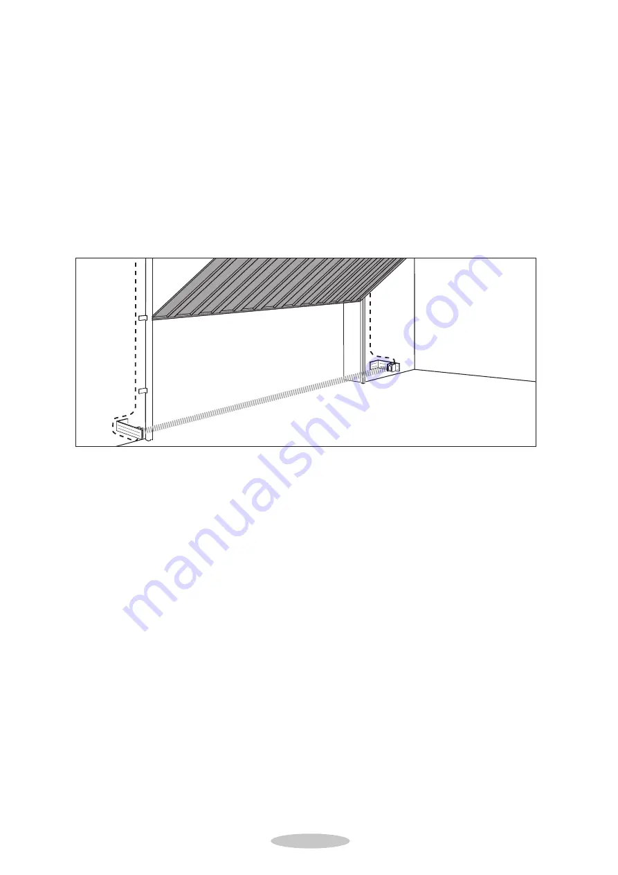
Beam Break

For additional safety we recommend a Beam Break is installed. If the INFRA-RED BEAM
is broken by a person or object whilst the door is closing, it will automatically reverse to the
fully open postion without actually having touched the closing door itself.

Summary of Contents for DC650NII

Page 1: ...II DC 650NII DC 650NII DC 650NII DC 650NII DC 650NII DC 650NII DC 650NII DC 650NII DC 650NII DC 650NII DC 650NII DC 650NII DC 650NII DC 650NII DC 650NII DC 650NII DC 650NII DC 650NII DC 650NII DC 650N...

Page 2: ...g garage door Repeat the test once a month and make any needed adjustments see Advanced Settings Menu b and Menu c on page 20 of this manual Installation and wiring must be in compliance with your loc...

Page 3: ...sure maximum quality and safety In order to prevent damage to the garage door or garage door operator and to comply with the Machinery Directive it is important that this operator is fitted in accorda...

Page 4: ...lly reverse if the door is not fully closed within 88 seconds Safety Stop Opening door will immediately stop when obstructed by person or object Beam Break For additional safety we recommend a Beam Br...

Page 5: ...the screws are tightly fastened N B Use 4 large Phillips HD selftap screws provided Lens cover should face rear of garage 2 Fit the red slider that re engages the emergency release and operator pull...

Page 6: ...age quick release a Pull cord a to disengage Carriage re engage remain disengaged See fig 3 b Move red slider b in direction of arrow to re engage carriage at next movement Start operator See fig 4 fi...

Page 7: ...or GRP doors only and the upper holes for all other doors Level and mount operator Disengage carriage from chain or belt Door may only be moved with moderate speed Connect operator pull bar to door br...

Page 8: ...etween highest travel point of door and rail Level and mount operator Disengage carriage from chain or belt Door may only be moved with moderate speed Connect operator pull bar to door bracket Note Re...

Page 9: ...TOR CONTROL PANEL INDICATIONS Your automatic door operator is provided with an easy to read LED display panel with 4 light icons and three program buttons Light icons 2 door fully open 4 door fully cl...

Page 10: ...te control in the Basic settings Changes in the extended programming level may only be carried out by specialists Advice To determine the error number add the figures of the irregularly flashing LED s...

Page 11: ...he door electrically once to open or close position Advice All menus can be reset by a RESET function to the original values set by factory Reset is activated by pressing and together for more than 30...

Page 12: ...e the OPEN and CLOSE buttons Advice The reference point has to be passed 1x Z will light up briefly when reference point has to be passed 1x Advice The reference point has to be passed 1x Z will light...

Page 13: ...operator is now in operational normal mode I MAKING ADJUSTMENTS To change the settings of an individual menu 1 Press for approximately 2 seconds until LED blinks 2 Repeatedly press until desired indic...

Page 14: ...Step 3 Actuate the desired button of the new hand transmitter and hold the button of the existing hand transmitter After 1 2 sec the LED on the new transmitter is glowing permanently Programming is te...

Page 15: ...elt drive boom it is not possible to reinstall a limit cam Motorhead side Reference point clip should be 960 mm 30 mm from motorhead side Carriage Door side Chain clip can be manually connected Belt c...

Page 16: ...ternal relay optional 2 external relay optional W20 Receiver HF module output 24V 24 VDC 50mA max 0V masse ground RC Contact bk black bn brown or orange rd red gr green bl blue ye yellow Wall control...

Page 17: ...response on impulse Error 10 Temporarily isolate cabled key switches or interior push buttons from control unit Remove plug insert plug and look for cable fault Connecting terminals for IMPULSE butto...

Page 18: ...nsitivity of power limit 8 K H S Learned power limit 8 K H S Power limit self monitoring unit 8 K H S Voltage monitoring is active 7 K H Photocell self monitoring unit not o k 7 K H Excess travel stop...

Page 19: ...he 2nd programming level A setting should always be carried out as soon as a less sensitive setting has to be chosen due to door travel properties caused by site conditions as otherwise the automatic...

Page 20: ...s set automatically Only change it if necessary error No 5 When increasing the set value the max force in OPEN direction is increased and thus the sensitivity of the automatic cut out is reduced Atten...

Page 21: ...lues may be necessary 1 LED F and LED H blink and all others are illuminated 2 By pressing and set the desired maximum closing force Each illuminated LED represents 1 8 of the maximum total force 3 On...

Page 22: ...u e SET START UP PHASE 8 1 Make sure LED K is blinking and all other are illuminated 2 Use or to change start up warning phase a No start up warning b 2 second start up warning with external signal re...

Page 23: ...ss to store and to finish setting up the operator speed and level 2 settings The LEDs will automatically turn off starting at LED 8 and ending at LED 2 Operator is now in operational normal mode recog...

Page 24: ...Tel 01280 703022 Fax 01280 702195 MAIN UK EIRE DISTRIBUTOR DC 650N II Garage Door Operator Connected loads 230 V 200 W in operation with lighting 3 9 W out of operation without lighting Door travel sp...

Page 25: ...r 2 sec until LED X blinks and all others are illuminated h g j h g j j I Q U S Z E T R I Q U W Z E T F I Q J W H E T R 8 Q 7 W 6 E 5 4 I 1 7 2 6 3 5 4 Menu 2 Programming door closed position Menu 1 P...

Page 26: ...4 8 Q 7 W 6 C 5 F 8 Q 7 W 6 C 5 4 8 Q 7 W 6 C 5 F 8 Q 7 W 6 C 5 4 8 Q 7 W 6 C 5 F I Q U X Z E T R I A U S Z E T R I Q U S H E T R I Q U W H E T F I Q U W H E T R K Q J W Z E T R 8 Q 7 W 6 E 5 4 I 1 7...

Page 27: ...ction arm and appropriate safety devices etc and not until the complete installation has been declared to be in conformity with the provisions of the Machinery Directive The technical files for the op...

Page 28: ...oor and that any safety devices provided are sui table for the application and are all working satisfactorily This will permit the nominated person to attach a CE label identifying the name of the ins...

Reviews: