background image

In the picture to the 

right you will see the 

connection of the 

temperature sensor 

(red tabbed lead) into 

the pin marked TEMP.  

The Speed Sensor Coil 

(Black tabbed lead) is 

connected to the pin 

marked SPEED.  The blue 

Data cable is connected 

in to the ‘CNTL’ plug.  All 

of these leads need to be 

fed through the rubber 

grommet in the wall of the 

control box. 

The smaller inlaid picture below shows the JMP3 and JMP1 plug switches. 

These, when set correctly, determine what fan size the PCB board will 

operate. 

Because there are three (3) different size fans that this one control box can 

operate it is important to set the control box to the right sized fan. The plugs 

location on each of the 3 sets of pins is critical in the fans correct operation. 

It is important that the control box is UNPLUGGED from power when 

you change the positions of these plugs!! If you change these plugs when 

the control box has power flowing to it, will BLOW the safety fuse and the 

control box will need to be returned to Cardiff Air.


As you can see in this 

picture the factory settings will be / JMP1 has been set in position 2 / and JMP3 

is in position 1. This tells us that the control box is setup to run the Cardiffair 

900 unit. 

•  For a Cardiff Air 550 

Unit JMP1 will need to be 

changed to Position 1

•  For a Cardiff Air 900 

Unit JMP1 will need to be 

changed to Position 2

•  For a Cardiff Air 1070 

Unit JMP1 will need to be 

changed to Position 3

JMP3 REMAINS IN 

POSTION NUMBER 1 

(ONE)  AT ALL TIMES.

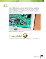
The next step in the installation process is to connect the Louvre Actuator 

Assembly motor to the PCB.

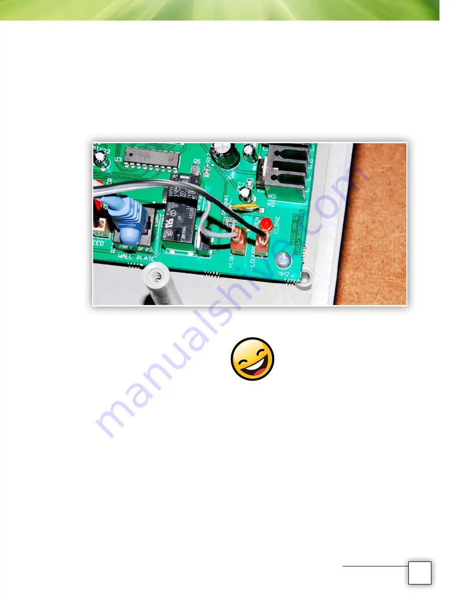
Feed the figure eight cable through the rubber grommet along with the speed 

sensor pick up coil, temperature sensor and RJ45C data cable. The figure eight 

cable is grey and grey with a black trace. Connect the grey lead to the positive 

terminal marked on the PCB. Connect the grey with the ‘Black’ trace to the 

negative terminal. Double check that all connections are secure and place the lid 

back on the top of the control box. 

Plugged in Louvre Actuator neg and pos shown.

Complete!

You have now successfully completed the installation for a Cardiffair Motor Unit.

32

Motor Installation

33

Motor Installation

20

21

Summary of Contents for 1070 Vantage

Page 1: ...COOLING AUSTRALIAN S FOR OVER 30 YEARS FAN MOTOR LOUVRE INSTALLATION MANUAL u...

Page 2: ...Fan FAN ASSEMBLY Tools Required Box Contents Cardiffair 900 Elite Fan Motor Mounting Plate Bend Bar Fan Position Bearing Housing Fan Tightening Installation Materials MOTOR INSTALLATION Tools Require...

Page 3: ...2 6 8 0 0 1 2 5 7 9 0 1 2 3 4 5 5 6 1 Motor Installation FAN ASSEMBLY Cardiffair Fan Assembly Instructions for 900 1070 Fan Units...

Page 4: ...Ring Open Ender 13mm Ring Open Ender Adjustable Wrench 3mm Allen Head Key Stanley Knife Cable Ties any small size will do Level Tools required to install motor and control box Contents inside box rev...

Page 5: ...how the bearing housing motor mounting bracket fan belt assembly nuts and bolts pulley and contents page Contents of the complete fan box unpacked and laid out Contents show 4 bend bars fan shroud fan...

Page 6: ...come in stainless steel and galvanised applications Fan should be placed on a table for ease of assembly at a comfortable working height Contents of plastic bag contained in parts box The contents of...

Page 7: ...as 3 holes in the side closest to the foot of the bend bars This identifies the motor mounting plate bend bar You should have 2 bend bars that have a set of holes along the straight shaft of the bar t...

Page 8: ...and lay it over the fan in the middle Then collect a bearing housing bend bar 1 of 2 supplied and lay it underneath the hand of the motor mounting plate bend bar What you effectively have is left and...

Page 9: ...shroud up through the hole the nylon spacer and up through the foot of the bend bar Place the washer over the bolt and do the nylock nut up finger tight Let go of the bend bar The smallest bolt a wash...

Page 10: ...bend bar over the shaft of the bend bar on the right A good way to ensure assembly goes right every time is to start with the mounting plate bend bar first be sure that the bearing housing bend bars a...

Page 11: ...surface with WD40 The shaft and the pulley and fan bosses are designed to be a slide fit Do not under any circumstances use a hammer Once the shaft of the bearing housing has been located flush on th...

Page 12: ...e formed by the bend bars to the outside Place a washer and a nylock nut on each bolt By using the nylock nuts and washers on the outside makes it easier to service the fan unit down the track This ph...

Page 13: ...shroud Once the cardboard is in place then pass the remaining 4 bolts down through the fan bend bars and use a nylock nut and washer underneath Once all four bend bar bolts are in place the fan is st...

Page 14: ...is done properly as the fan will foul the shroud if not done correctly To tighten the bolts in the correct order start at the bearing housing bolts marked as indicated and tighten the diagonals one at...

Page 15: ...tually doing is working from the inside out tightening the bearing housing first then the bend bars and finally the fan shroud The last bolts to be tightened are the fan shroud bolts These were the fi...

Page 16: ...e now three quarters away from completing a fan assembly Locating the motor mounting plate is easy this picture shown is for the 900 fan unit Insert the counter sunk screws into the appropriate mounti...

Page 17: ...fference is the 1070 unit has the larger nuts behind the mounting plate and the mounting holes used are closest to the edge of the bracket 23 15 Fan Assembly 900 FAN UNIT NO SPACERS 1070 FAN UNIT HAS...

Page 18: ...have a vibration damper The easiest way to insert these dampers is to lightly spray the underside of the venturi ring with WD40 and press the damper up through the hole It s extremely hard to insert...

Page 19: ...17 Fan Assembly...

Page 20: ...18 Motor Installation...

Page 21: ...MOTOR INSTALLATION Cardiffair motor installation and MKIII variable speed control box to suit ALL Cardiffair model units 550 900 and 1070 fans 19 Motor Installation...

Page 22: ...ad Key Stanley Knife Cable Ties any small size will do Level Note The installation of this motor is the same for all types of motors that can be fitted to a Cardiffair Unit For the purpose of this man...

Page 23: ...the 900 and 1070 units The 550 mount plate is different again but you are limited in the size of the motor you can use for the 550 unit NB 550 fan unit already has the motor mounting plate attached Re...

Page 24: ...bolt that has been fed through the mounting plate Once all the nuts and washers have been loosely fastened into place slide the motor pulley onto the motor shaft and run the V belt over the fan and mo...

Page 25: ...as you are doing up the first mounting bolt Make sure you can get all of your spanners onto each nut and bolt when you are tightening them up The reason for the slight tilt is that the motor is rubbe...

Page 26: ...ightened make sure that any cable is then moved away from the fan blades and Venturi ring If necessary tie the motor cable back using cable ties or a good adhesive tape See picture below All of the mo...

Page 27: ...arked with letters from A to F These are A The wall switch B The blue data cable Cat5 or patch lead This links the wall switch to the control box C Temperature pickup coil D Speed sensor disc E Speed...

Page 28: ...sor disc down the motor shaft You may need to use some WD40 to assist in sliding the disc in place Use the 3mm Allen Head Spanner to tighten up the grub screw in the sensor disc Be sure you don t over...

Page 29: ...er like the picture below shows Then unscrew the speed sensor coil from the speed sensor bracket What you are doing is creating a thread in the predrilled holes so that it is easier to locate and fix...

Page 30: ...sensor mounting bracket remove the screws and slide the mounting bracket underneath Slide the spring washers over the screws provided and fix the speed sensor pick up coil in place Note there should...

Page 31: ...e sensor disc and the pick up coil is not critical Once this step has been done slide the motor pulley back down into place on top of the speed sensor disc Because you have already adjusted the belt t...

Page 32: ...and in place select a suitable area for the MKIII control box to be mounted into place Depending on the installation you can screw fix the MKIII control box anywhere so long as the motor lead and the...

Page 33: ...box The motor plug and capacitor will fit neatly into the junction box You will need to cut ONE end out of the junction box so that the motor plug cord can come out See pictures below Fix the junctio...

Page 34: ...n The plugs location on each of the 3 sets of pins is critical in the fans correct operation It is important that the control box is UNPLUGGED from power when you change the positions of these plugs I...

Page 35: ...figure eight cable is grey and grey with a black trace Connect the grey lead to the positive terminal marked on the PCB Connect the grey with the Black trace to the negative terminal Double check tha...

Page 36: ...LOUVRE ACTUATOR Assembly and Installation 34 Louvre Actuator Assembly...

Page 37: ...m ring spanner tighten both screws up The holes will have a little bit of play so be sure to stand the mount plate vertical when tightening up the screw heads 35 Louvre Actuator Assembly When connecti...

Page 38: ...ND in the ARM to ensure there is no fouling of the Louvre Panel Connecting Bar and the Louvre Actuator Connecting Arm The picture below shows the bend in the arm This can be done quite simply by hand...

Page 39: ...ply slide the screw on the arm through the hole in the Drive Arm and place the nylock nut on the end of the screw and tighten up Note When tightening up the nylock nuts on the connecting arm make sure...

Page 40: ...mpany in the HIA Greensmart Program Cardiff Air Control Systems Pty Ltd Family owned and operated Unit 3 28 Cavendish Road Coorparoo Qld 4151 PO Box 1541 Coorparoo DC Qld 4151 Ph 1800 800 943 Fax 07 3...

Reviews: