36
Louvre Actuator Assembly
37
Louvre Actuator Assembly
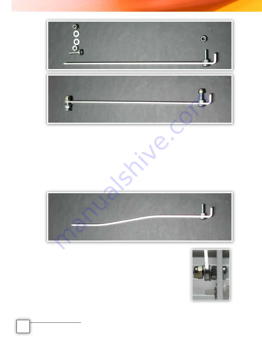
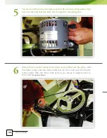
This picture shows the Connecting Bar and all of the required attachments.
The 90 degree bend on the bar goes to the
MOTOR
Drive Arm. The end
with the hole is attached to the Louvre Panel Connecting Bar. There is a pre
drilled hole on the connecting bar for the correct position of the Louvre Panel
when the Louvre Panel is open and closed. From the factory the Louvre Panel
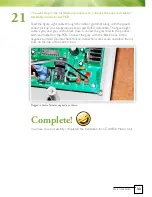
Connecting Arm is straight. What you need to do is put a slight
‘BEND’
in the
ARM to ensure there is no fouling of the Louvre Panel Connecting Bar and the
Louvre Actuator Connecting Arm. The picture below shows the bend in the
arm. This can be done quite simply by hand.
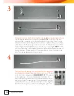
The next important step is to ensure the Connecting Arm
and Connecting Bar are attached the correct way.
This step
is the one that is always done
INCORRECTLY
. The picture
to the right shows the correct installation. Note that the
screw and nut (supplied on the arm) are attached directly to
the Louvre Panel Connecting Bar. This is followed by a small
washer, then the Louvre Actuator Assembly Connecting Arm,
then the remaining small washer, followed by the nylock nut.
3
4
Once the connecting arm is in place, attach the other end of the arm to the
Louvre Actuator Motor Drive Arm.
Make sure that the screw and nut are tight,
then simply slide the screw on the arm through the hole in the Drive Arm and place
the nylock nut on the end of the screw and tighten up.
Note:
When tightening up the nylock nuts on the connecting arm, make sure that
they are not over tight; this applies to both ends of the arm. In other words leave a
little gap between the washers and the nuts so as the arm can travel freely when in
operation.
5


