13
THE INTEGRATED CARDIN SYSTEMS ARE DESIGNED AND BUILT ONLY TO BE
USED IN MADE TO MEASURE METALLIC STRUCTURES. CARDIN ELETTRON-
ICA DO NOT GUARANTEE PRODUCTS THAT HAVE BEEN INSTALLED IN A
WAY THAT DOES NOT CONFORM TO THE SUPPLIED INDICATIONS.
5) Do not allow children to play with the operator or with the control
devices.
6)
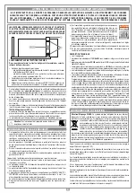
At least two warning signs
(similar to the example on the right)
should be placed, where they can be easily seen by the public,
in the area of the system of automatic operation. One inside the
property and one on the public side of the installation. These
signs must be indelible and not hidden by any objects (such as
tree branches, decorative fencing etc.). Make sure that the end-user is aware that
children and/or pets must not be allowed to play within the area of a gate instal-
lation. If possible include this in the warning signs
7) Ahead of the automation a means of disconnection from the power supply must
be installed which has an opening distance on the contacts of all the poles and
ensures that the power supply is completely cut off under the conditions of a
category III overvoltage situation.
8) A correct earth connection is fundamental in order to guarantee the electrical safety
of the machine
9) If you have any questions about the safety of the gate operating system, do not
install the operator. Contact your dealer for assistance.
TECHNICAL DESCRIPTION
• The set consists of:
1 geared motor
100/SLi824
with an incorporated encoder without onboard electronics.
1 electronic programmer
CC824
with NiMH batteries, a battery charger and an inte-
grated S449 radio frequency module.
• The geared motor is powered by
24 Vdc
and is fitted with a double-reduction kinetics
system immersed in permanently fluid grease .
• The emergency manoeuvre is carried out by means of an efficient manual release
system integrated into the geared motor.
• The motor is connected to the electronic programmer by means of a 6 wire fast-
fitting cable.
• The electronic programmer is aimed at the management of 24V encoder controlled
motors for sliding gates that allow gate-positioning control. Repositioning takes place
automatically whenever foreign objects get in the way of the gate as it is moving. If
the motor release system has been activated a sensor positioned on the mechanical
components will force the programmer to carry out automatic repositioning the next
time a command is given.
The electronic control unit is completed by the anti-crush and
"soft start" and "soft
stop"
functions.
The electronic components are housed in a shock-proof plastic container IP55 and
are factory fitted with a slot-in battery charger, NiMH buffer batteries driving the gate
during emergencies, an RF module for remote control and a
Liquid Crystal Display
(LCD 16 digits x 2 lines) which allows all the running functions and the number of
manoeuvres carried out by the automation to be monitored as well permitting rapid
parameter and function mode setting.
Attention!
Only for EU customers -
WEEE marking
.
This symbol indicates that once the products life-span has expired
it must be disposed of separately from other rubbish. The user is
therefore obliged to either take the product to a suitable differential
collection site for electronic and electrical goods or to send it back to
the manufacturer if the intention is to replace it with a new equivalent version of
the same product. Suitable differential collection, environmental friendly treatment
and disposal contributes to avoiding negative effects on the ambient and conse-
quently health as well as favouring the recycling of materials. Illicitly disposing of
this product by the owner is punishable by law and will be dealt with according
to the laws and standards of the individual member nation.
During the opening/closing manoeuvre check for correct operation and activate the
emergency stop button in case of danger.
During blackouts the gate can be released and manually manoeuvred using the sup-
plied release key (see manual release on pag. 14).
Periodically check the moving parts for wear and tear and grease if required using
lubricants which maintain their friction levels unaltered throughout time and are suitable
for temperatures of
-20
to
+70°C
.
In case of failure or operational anomalies switch off the power at the mains do not
attempt to repair the appliance yourself.
Periodically check the correct operation of all safety devices (photoelectric cells etc.).
Eventual repair work must be carried out by specialised personnel using original
spare parts.
The appliance is not suitable for continuous operation and must be adjusted according
to the model (see technical data on pag. 44).
Q
IMPORTANT SAFETY INSTRUCTIONS
USER INSTRUCTIONS
APERTURA AUTOMATICA
NON AVVICINARSI
NON PERMETTERE A BAMBINI O AD
ANIMALI DOMESTICI DI SOSTARE NEL
RAGGIO D'AZIONE DEL CANCELLO
ATTENZIONE
ATTENTION! IMPORTANT SAFETY INSTRUCTIONS
READING THESE INSTRUCTIONS IS IMPORTANT FOR PERSONAL SAFETY. READ THE FOLLOWING REMARKS
CAREFULLY BEFORE PROCEEDING WITH THE INSTALLATION. PAY PARTICULAR ATTENTION TO ALL THE PARA-
GRAPHS MARKED WITH THE SYMBOL
IN THIS ORIGINAL INSTRUCTION MANUAL. NOT READING THESE
IMPORTANT INSTRUCTIONS COULD COMPROMISE THE CORRECT WORKING ORDER OF THE SYSTEM AND
CREATE DANGER SITUATIONS FOR THE USERS OF THE SYSTEM. SAVE THESE INSTRUCTIONS FOR FUTURE USE.
A
B
C
CC824
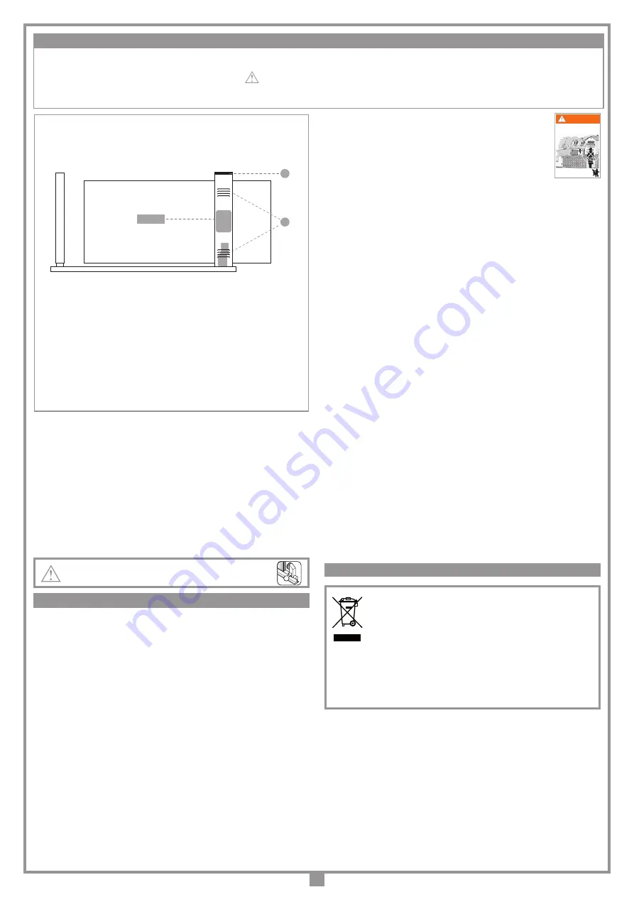
It therefore follows that the structure should be constructed in such a way
as to guarantee the following characteristics:
• Suitable for housing electronic appliances;
- the upper part must be completely sealed, so as not to allow water infiltra-
tion (IP55) (det. A);
- Air vents should be fitted in both the upper and lower parts of the columns
in order to avoid condensate build up (det. B);
• Conformity with the dimensional and structural characteristics as stipulated
by good building practice;
• The end structure should respect the parameters as laid down by the stand-
ards and regulations in force UNI EN 12453 with regard to maintaining safety
conditions during the use of motorized gates and doors.
• These instructions are aimed at professionally qualified "
installers of electrical
equipment
" and must respect the local standards and regulations in force. all
materials used must be approved and must suit the environment in which the
installation is situated.
• All maintenance operations must be carried out by professionally qualified techni-
cians. Before carrying out any cleaning or maintenance operations make sure the
power is disconnected at the mains.
• This appliance must be used exclusively for the purpose for which it has been
made. "i.e.
for the automation of sliding gates
"
105/SLi824 max. weight 300 kg.
• Any non authorised modifications are to be considered improper and therefore
dangerous.
• The motor can be positioned either to the
left
or to the
right
of the passageway.
Caution!
The installation of both anti-derailment buffers is
absolutely obligatory.
• This appliance must never be used by people (including children) with physical,
sensory or mental disabilities or by people without specific knowledge and expe-
rience in its operation unless they are able to benefit from the experience or are
being taught to use the appliance whilst being safeguarded by the presence of
somebody responsible for their safety.
• Before installing make sure that the guided parts are in good condition, correctly
balanced and that they open and close correctly.
• Avoid becoming trapped between the moving parts and the fixed parts during the
opening and closing movements.
• The motor’s power cable must be made of polychloroprene in conformity with the
international standard 60245 IEC 57.
It is the responsibility of the installer to make sure that the following public safety
conditions are satisfied:
1) Ensure that the gate operating installation is far enough away from the main road to
eliminate possible traffic disruptions and that the size of the gate, the distance from the
road and the work cycle speed can in no way interfere, causing possible traffic hazards.
2) The motor must be installed on the inside of the property and not on the public
side of the gate. The gates must not open onto a public area.
3) The sliding gate operator is designed for use on gates through which vehicles
are passing. The gates must not be fitted with pedestrian access doors.
4) The minimum controls which may be installed are OPEN-STOP-CLOSE, these
controls must be installed at a height between
1,5
and
1,8 m
and in a location
not accessible to children. Controls installed externally must be protected by a
safety device inhibiting unauthorised use.


