background image

17

Before connecting the appliance make sure that the voltage and fre-

quency rated on the data plate conform to those of the mains supply. 

•  The appliance works off a single phase 

230 V 50 Hz 

power supply (see 

wiring diagram).

•  The geared motor must be earthed, to this end use the binding post 

marked   which can be found on the wiring box.

•  Do not use cables with aluminium conductors; do not solder the ends 

of cables which are to be inserted into the binding posts; use cables 

which are marked 

T min 85°C

 and are resistant to atmospheric agents.

•  The power cable must have enough slack to make sure it is not pulled 

tight during normal operation.

•  The power cable must not be wound around any of the appliances 

components and must not be cemented into the wall.

 An double pole circuit breaker with a minimum of 

3 mm

 between 

the contacts must be installed between the electronic programmer 

and the mains supply.

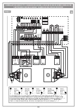
•  Connect the supplied capacitor between the live wires 2 and 3 of the 

geared motor (fig. 19-21  pag. 9-11).

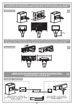
Power cable rubber sealing cap

1

) Fit the sealing cap on to the power cable 

and slide it down enough to allow you to 

connect the cable to the terminal board. 

2

) Fasten down the cable using the cable 

clamp. 

3

) Close the cover and slide the sealing cap 

up over the cable entry opening.  

This action is extremely important and will
guarantee a protection grade of IP44.  

IMPORTANT!

 The geared motor is not fitted with a torque limiter. 

Only use an electronic programmer which has a torque limiter with 

maximum force at the head of the gate equal to 

150 N

 (local stand-

ards and regulations in force).

SETTING THE MOTOR TORQUE (see electronic programmer)

When carrying out the installation you are advised to use a Cardin 

electronic programmer fitted with a torque limiter.

The Cardin programmers optimise the correct working order of the "machine" 

(motorised gates/doors) and guarantee full power maximum thrust at the 

start of the opening/closing manoeuvre).
The programmer also guarantees that the effective torque fed to the system  

will be that selected by the operator in the electronic programmer. 
The choice of settings depends on the weight and size of the gate leaf/door 

and the different environmental conditions on-site.

You are reminded that the standards and regulations in force unequivo-

cally require  that the torque be set to a level suitable for the system.   

Correctly choosing the torque will guarantee maximum security and long 

life for the mechanical components. 

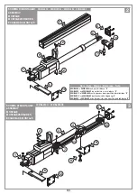
SETTING THE MECHANICAL TRAVEL LIMIT (fig. 3 pag. 3)

The model 

200/BL203C - 200/BL203CE

 is fitted with adjustable mechani-

cal travel limits "

7

" and "

10

". 

Loosen the fastening screws and move the rings "

7

" and "

10

" to the 

desired opening and closing positions then tighten them carefully. 

SCALA: 1:2

Prodotti Technocity 

BL202    

01-07-99

DI0131

Description :

Product Code :

Date :

Drawing number :

P.J.Heath

CARDIN ELETTRONICA S.p.A  - 31020 San Vendemiano (TV) Italy - via Raffaello, 36 Tel: 0438/401818 Fax: 0438/401831

Draft : 

All rights reserved. Unauthorised copying or use of the information contained in this document is punishable by law 

Collegamento gommino protezione

12

3

12

3

12

3

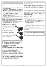
Releasing the gate should only be carried out when the motor has stopped 

because of blackouts.
To release the gate use the plastic key supplied with the appliance. It 

should be stored in an easily accessible place, at home or on the appli-

ance itself using the key slot (pos. 5 fig. 12).

To release the gears

-  open the lock mechanism cover by pressing on the sides (fig 12a-12b);
-  insert the release key and turn it through about 30 degree (fig. 12c). 

The gears will be released and the lock cylinder will rise;

-  if you wish leave the gears released, just close the lock cylinder cover 

(fig. 12e).

To lock the gears

-  remove the key (fig. 12d), close the cover and press down with the 

palm of your hand until the gears are locked;

-  keep the key in a safe place.

Note: To make the operation easier the gate can be moved slightly if 

required.

Don't force the locking mechanism, if you encounter resistance 

move the gate slightly to allow the cogs to slot together more 

easily within the geared motor.

  ELECTRICAL CONNECTION 

(fig. 19-21 page 9-11)

  MANUAL RELEASE MECHANISM 

(fig. 12, page 6) 

Summary of Contents for 200/BL203

Page 1: ...rtanti Pag 12 Istruzioni per l uso Pag 12 Istruzione per l installazione Pag 13 Collegamento elettrico Pag 14 Sblocco manuale Pag 14 Caratteristiche tecniche Pag 28 ATENCI N Antes de iniciar la instal...

Page 2: ...e photo lectrique ext rieure 5 Clignoteur 6 S lecteur cl 7 Serrure lectrique 8 Antenne C ble coaxial RG58 Imp dance 50 9 Interrupteur omnipolaire avec ouverture des contacts d au moins 3 mm 10 C ble d...

Page 3: ...ontained in this document is punishable by law 1 2 5 6 9 3 7 10 8 12 4 11 SCHEMA DI MONTAGGIO ASSEMBLY MONTAGE MONTAGEVERFAHREN ESQUEMA DE MONTAJE 200 BL203 200 BL203L 200 BL352 200 BL452 200 BL352 e...

Page 4: ...MENSIONI D INGOMBRO EXTERNAL DIMENSIONS DIMENSIONS D ENCOMBREMENT AUSSENABMESSUNGEN DIMENSIONES M XIMAS Prodotti Technocity DI0101 Description ber Vista pistone 352 1096 80 745 1025 80 12 59 90 A CORS...

Page 5: ...2 7 38 5 17 7 20 8 110 180 210 0 80 90 20 30 6 35 39 9 45 7 24 4 28 110 200 180 0 80 90 20 33 38 8 33 38 8 16 19 110 X Spessore da aggiungere a cura dell installatore X Spacer to be added by the insta...

Page 6: ...h CARDIN ELETTRONICA S p A 31020 San Vendemiano TV Italy via Raffaello 36 Tel 0438 401818 Fax 0438 401831 Draft All rights reserved Unauthorised copying or use of the information contained in this doc...

Page 7: ...ights reserved Unauthorised copying or use of the information contained in this document is punishable by law FISSAGGIO STAFFA POSTERIORE A PILASTRO FITTING THE REAR BRACKET TO A COLUMN FIXATION DE LA...

Page 8: ...max SCALA 1 2 Prodotti Technocity BL202 SERIE 12 10 98 DI0096 Description Product Code Date Drawing number P J Heath CARDIN ELETTRONICA S p A 31020 San Vendemiano TV Italy via Raffaello 36 Tel 0438 4...

Page 9: ...8 TAL CSER 26 25 24 23 22 21 20 19 18 17 16 15 38 37 36 35 34 33 32 31 30 29 28 27 TA ANTENNA TC TD FTC_S FTC_I NC NC NC TB COMUNE COMUNE COMUNE COMUNE COMUNE 1 14 13 12 11 10 9 8 7 6 5 4 3 2 FCC_1 FC...

Page 10: ...bridge if unused FCA OPENING TRAVEL LIMIT bridge if unused FTC_S STOP PHOTOCELL bridge if unused FTC_I INVERTING PHOTOCELL bridge if unused BSP PASSIVE SAFETY INPUT bridge if unused LP FLASHING WARNI...

Page 11: ...ING FCC CLOSING TRAVEL LIMIT bridge if unused FCA OPENING TRAVEL LIMIT bridge if unused FTC_S STOP PHOTOCELL bridge if unused FTC_I INVERTING PHOTOCELL bridge if unused LP FLASHING WARNING LIGHTS 24Va...

Page 12: ...truso Particolari sblocco in plastica antiurto Riduttore con ingranaggi in acciaio racchiusi in semigusci di alluminio pressofuso BL203 202L 202C Riduttore epicicloidale ad alta silenziosit e vite sen...

Page 13: ...ATTENZIONE Il motore deve essere montato sul cancello con i fori scarico condensa A rivolti verso il basso vedi figura Fissare con l apposito perno 1 l attuatore alla staffa di coda 5 figura 2 a pagi...

Page 14: ...o 3 mm Collegare tra le fasi 2 e 3 del motoriduttore fig 19 21 pag 9 11 il condensatore fornito di serie Gommino protezione ingresso cavo di alimentazione 1 Inserire il gommino nel cavo di ali mentazi...

Page 15: ...pliancemustbeusedexclusivelyforthepurposeforwhichithasbeen made i e fortheautomationofhingedgates withoneortwogateleaves The unit may be fitted both to the right and to the left of the passageway This...

Page 16: ...otor must be installed on the gate with the humidity drain holes A facing downwards see drawing Fix the arm to the rear mooring bracket 5 using the retaining pin 1 fig 2 pag 3 and the front bracket 6...

Page 17: ...ive torque fed to the system will be that selected by the operator in the electronic programmer The choice of settings depends on the weight and size of the gate leaf door and the different environmen...

Page 18: ...t tre certifi s et tre adapt s aux conditions atmosph riques du lieu d implantation Les travaux de maintenance ne doivent tre effectu s que par un personnel qualifi Avant une quelconque op ration de n...

Page 19: ...pilier fig 13 page 7 en respectant les cotes A et B apr s avoir contr l la position du gond par rapport au pilier cote C fig 8 page 5 et en fonction du type d ouverture r aliser ATTENTION Le moteur d...

Page 20: ...COUPLE MOTEUR voir programmateur Pour r aliser l installation il est conseill d utiliser un des programma teurs Cardin dot s de r glage du couple Les programmateurs Cardin optimisent le fonctionnemen...

Page 21: ...Ger te d rfen nur f r die Verwendung eingesetzt werden f rdiesieausdr cklichkonzipiertwurden d h DenAntriebvon Drehtoren mit einem oder zwei Torfl geln Die Vorrichtung kann sowohl auf der linken als a...

Page 22: ...g des Torfl gels im geschlossenen Zustand notwendig Die Sicherheitsfreir ume zwischen den festen und beweglichen Teilen kontrollieren auf der gesamten H he und ffnungsweite der Tores einen Frei raum v...

Page 23: ...g zu verwenden DieCardin SteuerungenoptimierendenBetriebder Maschine motorisierte Tore indem sie f r den Anlauf bei Beginn des ffnens und Schlie ens immer das h chste lieferbare Drehmoment gew hrleist...

Page 24: ...as de hasta 3 5 m y de 300 kg de peso cada una 200 BL452 Actuador electromec nico reversible para hojas de hasta 4 5 m y de 300 kg de peso cada una Motor monof sico en casquetes de aluminio fundido a...

Page 25: ...ber comprobado la posici n del gozne de la cancilla con respecto al pilar medida C fig 8 p g 5 y en funci n de la clase de apertura de la hoja que se quiere conseguir CUIDADO El motor se tiene que mon...

Page 26: ...R v ase programador Para la realizaci n del sistema se aconseja utilizar programadores Cardin provistos de ajuste del par del motor Los programadores Cardin optimizan el buen funcionamiento de la m qu...

Page 27: ...x x x x x x x x x x x x x x x x x x x x x x x x x x x x x x x x x x x x x x x x x x x x x x x x x x x x x x x x x x x x x x x x x x x x x x x x x x x x x x x x x x x x x x x x x x x x x x x x x x x x...

Page 28: ...230 230 230 Frequency Hz 50 50 50 50 50 50 Electrical input A 0 9 0 9 0 9 0 9 1 3 1 4 Power input W 220 220 220 220 270 310 Duty cycle 25 25 25 25 50 50 Travel mm 280 445 330 390 280 280 Force N 2000...

Reviews: