15
This device allows the propulsion unit to work during blackouts.
• The programmer has a built in charger for
NiMH 24V
batteries that is
managed by a dedicated micro controller. The control chip adjusts the
voltage according to the condition of the batteries.
To avoid the risk of overheating only use batteries supplied by
the manufacturer
SPN 999540
.
If the batteries show signs of damage they must be replaced
immediately.
The batteries must only be installed/removed by qualified
personnel. Used batteries must not be thrown into domestic
rubbish bins and they must be disposed of according to the
WEEE
standards and regulations in force.
• To indicate that the programmer is working off battery power when the
door is completely closed a hyphen flowing around the perimeter of
the display will appear.
If the battery is under charged a hyphen flowing around the lower half
of the display will appear. When the battery is almost completely flat the
symbol will appear and the programmer will be blocked.
• The unit returns to normal operation once the power supply brought back
on line. To use the batteries again they must first be allowed to recharge.
The battery charge time with batteries in good condition can take up to
a maximum of
12 hours
.
If the time required is greater you should consider replacing the batteries.
You are however advised to replace the batteries every three years.
• When the door has stopped the controlled external devices (
CTRL 24 Vdc
)
do not receive power in order to increase the autonomy of the battery.
When a command is received however (via radio or via cable) the pro-
grammer sends power to the controlled external devices and checks their
security status.
It follows therefore that the command will be carried out (security devices
at rest) with a one second delay to give time to restore the correct opera-
tion of the devices.
If after this period a security device is found to be in alarm the command
will not be carried out, power to the external devices will be cut off and
the programmer will return to stand-by.
Note!
If you wish to use an external receiver it must be wired to the binding
posts 13-14 (fig. 1) otherwise a command sent
via radio
will not be able to
activate the door.
• The self-sufficiency of the system when it is running on battery power
is dependent on the ambient conditions and on the load connected at
binding posts 13-14 (power is always routed there during blackouts).
When the batteries are completely flat (during blackouts) the
programmer will lose the position of the door and therefore when
power returns (after the first command given) you will have to
carry out the repositioning procedure (see page 12). For this
reason you should avoid leaving the
electronic programmer
without power
for lengthy periods (more than two days).
• You cannot enter the programming mode when running off battery
power.
• During blackouts the battery supplies power to both the logic and the
motor control parts of the programmer.
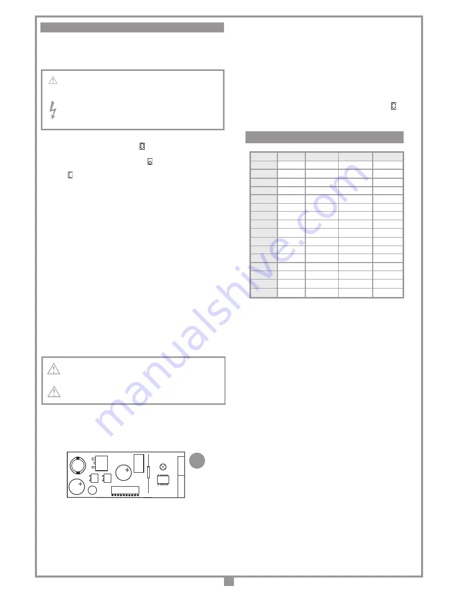
Slot-in battery charger
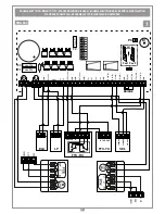
Signal LEDs (fig. 1)
L3
: lit when the battery is not properly connected during blackouts.
L2
: indicates the function mode as follows:
Off
: missing batteries or the electronic programmer is running off battery
power (during a blackout)
During the first 20 seconds of operation from the start up of the elec-
tronic programmer the battery charger is blocked and will not supply
any function indications;
Brief flashing
: voltage variation has been detected at the battery charger
binding posts (e.g. when the batteries are being connected or removed);
Single flashes
: this repeats every 2 seconds indicating that the batteries
are being topped up to maintain their level;
Remains lit
: the batteries are charging. The charge time can last from
5 to a maximum of 12 hours.
Battery check
With the door in the completely closed position and the display switched off:
Check that LED "
L2
" (battery charging) is off;
Switch off the power at the mains and make sure that the symbol appears
on the display. Give a movement command and measure the overall voltage
for both batteries. The reading should be about
24 Vdc
.
BATTERY POWERED OPERATION
CS1256B
DC0536
LD
Scheda di innesto
PRG424BC
14-02-2013
DC0536
Description :
Product Code :
Date :
Drawing number :
P.J.Heath
CARDIN ELETTRONICA S.p.A
- 31020 San Vendemiano (TV) Italy - via Raffaello, 36 Tel: 0438/401818 Fax: 0438/401831
Draft :
All rights reserved. Unauthorised copying or use of the information contained in this document is punishable by law
Scheda carica batteria
3
SC
TB
FTCS
FTCI
CSP
0 N.C.
N.C.
N.C.
N.C.
1
N.C.
N.C.
N.C.
8.2 k
Ω
2
N.C.
N.C.
8.2 k
Ω
N.C.
3
N.C.
N.C.
8.2 k
Ω
8.2 k
Ω
4
N.C.
8.2 k
Ω
N.C. N.C.
5
N.C.
8.2 k
Ω
N.C.
8.2 k
Ω
6
N.C.
8.2 k
Ω
8.2 k
Ω
N.C.
7
N.C.
8.2 k
Ω
8.2 k
Ω
8.2 k
Ω
8
8.2 k
Ω
N.C. N.C. N.C.
9
8.2 k
Ω
N.C.
N.C.
8.2 k
Ω
A
8.2 k
Ω
N.C.
8.2 k
Ω
N.C.
B
8.2 k
Ω
N.C.
8.2 k
Ω
8.2 k
Ω
C
8.2 k
Ω
8.2 k
Ω
N.C. N.C.
D
8.2 k
Ω
8.2 k
Ω
N.C.
8.2 k
Ω
E
8.2 k
Ω
8.2 k
Ω
8.2 k
Ω
N.C.
F
8.2 k
Ω
8.2 k
Ω
8.2 k
Ω
8.2 k
Ω
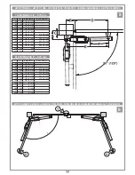
SELECTING THE SECURITY CONTACT TYPE


