


15
MANUAL MANOEUVRE (fig. 8)
Caution!
The manual manoeuvre should only be carried out if the equipment has
locked due to power failure or during installation of the automation.
Access to the release mechanism may be on the right or left according to the
installation. To reverse the boom opening direction, turn the release system
from the position det. A to det. B or viceversa, having loosened the 4 fastening
screws to do so. To access the mechanism, first remove the lock unit as shown
in sequence 1 and 2 of figure 8 / 8a, then release the motor using the hex wrench
provided (sequence 3 and 4). To relock the motor, carry out the reverse procedure.
ACCESS TO THE CABINET (fig. 9)
To access the mechanical / electronic controls using the key provided: turn
the key counter clockwise "
1
" and flip up the top cover "
2
". Tilt the panel "
3
"
outwards and then pull upwards to remove it "
4
". To reclose the top cover move
the left-hand lever lock upwards.
MECHANICAL ADJUSTMENT OF THE HORIZONTAL/VERTICAL
POSITION OF THE BOOM (fig. 10-10A)
Release the boom and lower it until the barrier is in the closed position "
1
".
Loosen the nut "
2
" by turning it counter clockwise, put the spirit level "
3
" on the
boom and turn screw "
4
" to adjust the horizontal position. With the boom in the
correct position "
5
", tighten the nut "
6
".
BALANCING THE BOOM (fig. 10b)
Release the boom, open the cabinet panel and turn the nut "
1
" counter clockwise
(approx.
5 turns
). Turn the spring counter clockwise to increase the tension or
clockwise to decrease the tension until the boom remains in position "
3
", i.e.
inclined by about
30° - 40°
. Having balanced the boom, tighten the nut "
4
".
Important remarks
•
The presence of the electrical current sensor does not dispense with the
obligation to install photoelectric cells and other safety devices foreseen by
the safety standards in force.
• Before connecting the appliance make sure that the voltage and frequency
rated on the data plate conform to those of the mains supply.
• The power cable must be made of polychloroprene in conformity with the
international standard
60245 IEC 57
(es. 3 x 1.5 mm
2
H05RN-F
).
• The cable may only be replaced by qualified technicians.
• An all pole trip switch with at least
3 mm
between the contacts must be
installed between the unit and the mains supply.
• Don't use cables with aluminium conductors; don't solder the ends of cables
which are to be inserted into the binding posts; use cables marked
T min
85°C
and resistant to atmospheric agents.
• The terminal wires must be positioned in such a way that both the wire and
the insulating sheath are tightly fastened.
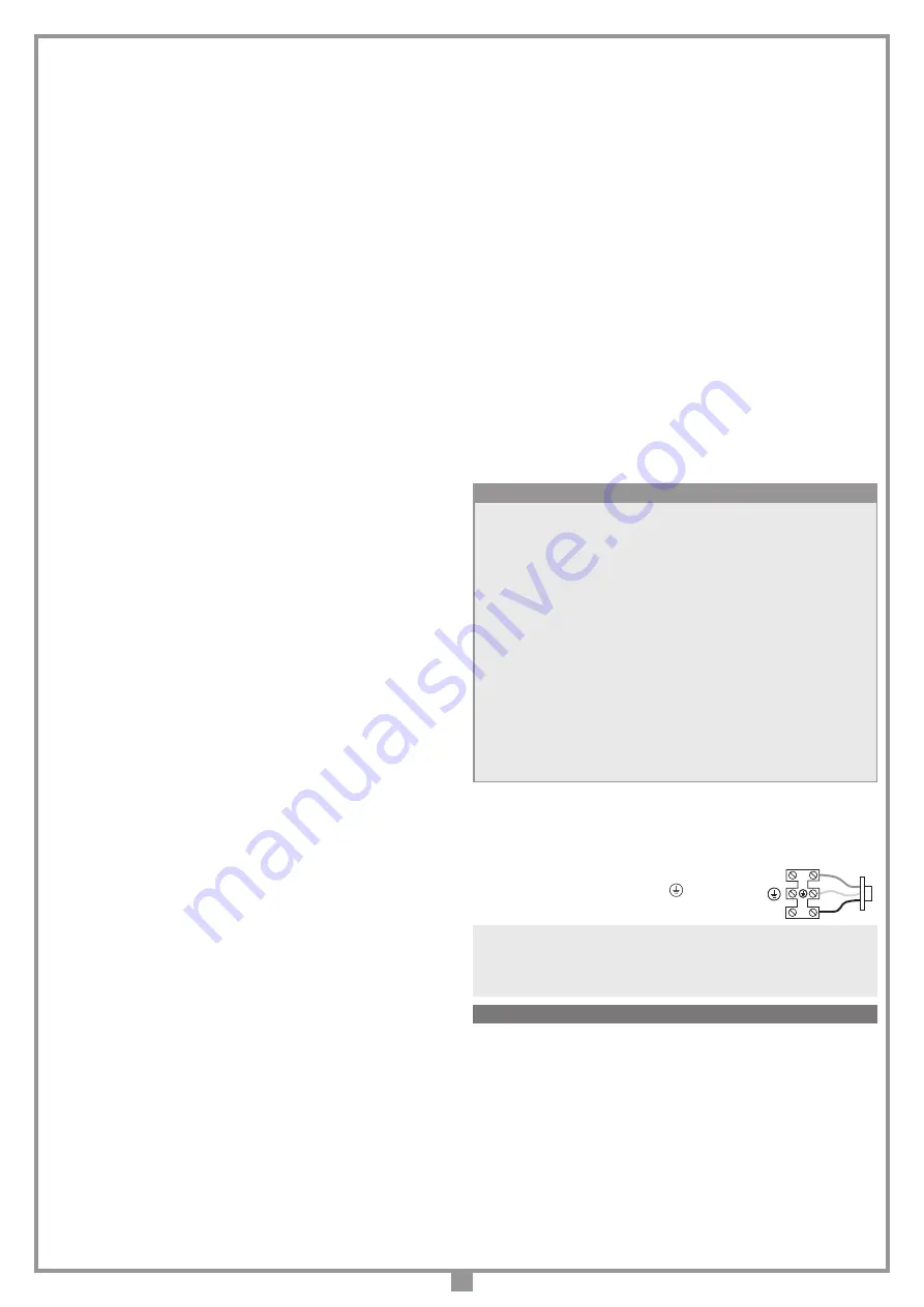
MAINS POWER SUPPLY CONNECTION
• Connect the control and security device wires.
• Run the mains power supply through the cable clamp located on the bottom right
of the main circuit board and to the separate 3-way terminal board:
- connect the
neutral
to binding post
N
- connect the
earth
to binding post
- connect the
live
to binding post
L
Electronic programming unit
Instructions for programming the ECU and battery powered operation can
be found in the
MULTI-ECU SOFTWARE
manual
ZVL608
supplied with the
automation.
Attention!
Before carrying out any cleaning or maintenance operations make sure
the power is disconnected at the mains, the motor power cables are disconnected
and the batteries have been disconnected. Eventual repair work must be carried
out by specialised personnel using original spare parts.
The motor does not normally require particular maintenance; in any case the
24
month
or
1 million manoeuvre
guarantee is only valid if the following controls have
been observed and eventual maintenance has been carried out to the machine
‘
road barrier
’:
- periodically check the moving parts for wear and tear and grease if required
using lubricants which maintain their friction levels unaltered throughout time
and are suitable for temperatures of
-20 to +70°C
;
- periodically check the correct operation of all safety devices (photoelectric cells,
safety edges etc.);
- check the battery charge level.
These checks must be written down as they are paramount in validating the guarantee.
FITTING THE UNIT (fig. 3/3b)
Prepare a cement base with the base plate and anchors "
C
" (optional) embedded.
The cable passage pipe "
D
" and the four threaded bolts
M12
must protrude (
30
mm
) from the base plate.
The base plate must be perfectly in square, its surface must be clean and the four
threaded
M12
bolts must emerge perpendicularly.
Note:
the cement base should preferably protrude
50 mm
out of the ground in
order to avoid water build up which could damage the appliance.
The size of the base plinth will vary according to the characteristics of the ground.
Remove the 4 self-locking nuts "
F
" from the four threaded bolts (used to fasten
down the anchors) and insert the base of the barrier "
E
".
Fasten down the barrier using the 4 self-locking nuts "
F
" and washers supplied
with the appliance.
It is also possible to fasten the barrier to an already existing cement base as long as
the thickness of the base is great enough to guarantee a strong hold for the rawlplugs.
We advise you to use the following type of rawlplug: "Steel anchor bolts
M12/Ø20
for heavy duty use".
SPRING INSTALLATION (fig. 4-4a)
To install the spring/s purchased with the barrier, apply some grease to the threaded
bar "
B
", locking nut "
C
" and swivel head"
E
". Screw the bar clockwise into the upper
part of the spring (indicated by the colour).
Grease the tie rod of the hook "
D
" and screw it a few turns counter-clockwise in the
lower uncoloured part of the spring "
A
".
Hook the resulting spring-assembly "
A
" with the hook to the lower part of the cabinet
"
F
", fix the head to the spring mechanism "
G
" using the nut and bolt "
H
".
• For installations with only one spring, first use the outermost hole, and if the spring
is too strong to balance the boom, gradually use the holes further in.
• For installations with two springs, unscrew the nut and bolt "
G
" insert the upper
fastening block into the boom holder "
H
", align to the central hole and fasten down
using the previously removed nut and bolt "
G
".
Screw in the threaded bar
"B
" to balance the boom-spring system and lock the rod
in place with the nut "
C
". Tighten the bolt "
E
" with a torque of at least
85-90 Nm
.
FITTING THE 3-5 METER BOOM (fig. 5-5a)
Mount the boom fixing base "
A
" onto the boom support hub "
B
" and lock with
the cable fastening bracket "
C
" using the screws "
D
" provided in the kit. Insert
the assembled unit onto the shaft "
E
", tighten the screw "
F
" and insert the grub
screw "
G
". Insert the safety edge connectors "
H
" into the bracket "
C
". With a
LED boom, also insert the connectors "
H1
". Insert the boom "
I
" and secure it
using the six screws and washers "
J
". Apply the hub cap "
K
" using the screws
"
L
" to secure it.
FITTING THE 6-8 METER BOOM (fig. 4b-5c)
Insert the safety edge connectors "
A
" into the bracket "
C
". With a LED boom,
also insert the connectors "
B
". Insert the boom "
D
" and secure it using the six
screws and washers "
E
". Apply the hub cap "
F
" using the screws "
G
" to secure it.
INVERTING THE BOOM OPENING DIRECTION 3-5 METERS (fig. 6a-6e)
To invert the boom opening direction from left (fig. 6a) to right (fig. 6e), release
the boom and move it to a vertical position "
A
" fig. 6b. With the spring "
C
" at rest
(
NOT UNDER TENSION
) unscrew and remove the nut and bolt "
B
". remove the
spring and the accessory box"
D
" if present (fig. 6c). Dismantle and reassemble
the boom to the right as shown in figure 5 and move it to a vertical position "
A
"
(fig 6c). Replace the spring "
C
" and insert and fasten down the nut and bolt "
B
"
(fig. 6d). Lock the boom and select
right-hand
boom from the
OPTIONS
menu.
INVERTING THE BOOM OPENING DIRECTION 6-8 METERS (fig. 6f-6j)
To invert the boom opening direction from left (fig. 6a) to right (fig. 6e), release
the boom and move it to a vertical position "
A
" fig. 6b. With the spring "
C
" at rest
(
NOT UNDER TENSION
) unscrew and remove the nut and bolt "
B
". remove the
spring and the accessory box"
D
" if present (fig. 6c). Dismantle and reassemble
the boom to the right as shown in figure 5 and move it to a vertical position "
A
"
(fig 6c). Replace the spring "
C
" and insert and fasten down the nut and bolt "
B
"
(fig. 6d). Lock the boom and select
right-hand
boom from the
OPTIONS
menu.
ASSEMBLING THE FIXED SUPPORT POLE (fig. 7-7b)
The fixed support pole is positioned at the head of the boom and functions as a
reference point for the closing of the barrier.
When the boom is moving it should never crash into the support pole but should
rest lightly against it instead.
Prepare a cement base in which the anchor plate "
S
" is to be inserted (make sure
that the
M8
threaded bolts are protruding by
30 mm
).
The base must be perfectly level, the threaded
M8
bolts must emerge perpendicularly
and be perfectly clean. Unscrew the four self-tapping screws on the four threaded
bolts (needed to block the anchors fig. 5a) and insert the base. Fasten down using
the supplied nuts and washers.
It is also possible to fix the base of the support to cement base or pavement which
already exists as long as it is wide enough and strong enough to take the anchor bolts.
We advise you to use the following type of rawlplug: "Steel anchor bolts
M8
/
Ø14
for heavy duty use".
N
L
Fissaggio placca inferiore
06-03-95
DI0286
Description :
Product Code :
Date :
Drawing number :
P.J.Heath
CARDIN ELETTRONICA S.p.A
- 31020 San Vendemiano (TV) Italy - via Raffaello, 36 Tel: 0438/401818 Fax: 0438/401831
Draft :
All rights reserved. Unauthorised copying or use of the information contained in this document is punishable by law
Collegamento motore
ELECTRICAL CONNECTION
MAINTENANCE


