background image

17


ATTENTION! IMPORTANT SAFETY INSTRUCTIONS 

READING THESE INSTRUCTIONS IS IMPORTANT FOR PERSONAL SAFETY. READ THE FOLLOWING REMARKS 

CAREFULLY BEFORE PROCEEDING WITH THE INSTALLATION. PAY PARTICULAR ATTENTION TO ALL THE PARA-

GRAPHS MARKED WITH THE SYMBOL 

 IN THIS ORIGINAL INSTRUCTION MANUAL. NOT READING THESE 

IMPORTANT INSTRUCTIONS COULD COMPROMISE THE CORRECT WORKING ORDER OF THE SYSTEM AND 

CREATE DANGER SITUATIONS FOR THE USERS OF THE SYSTEM. SAVE THESE INSTRUCTIONS FOR FUTURE USE.

Attention!

 Only for EU customers - 

WEEE marking

.

This symbol indicates that once the products life-span has expired 

it must be disposed of separately from other rubbish. The user is 

therefore obliged to either take the product to a suitable differen-

tial collection site for electronic and electrical goods or to send it 

back to the manufacturer if the intention is to replace it with a new 

equivalent version of the same product.

Suitable differential collection, environmental friendly treatment and disposal 

contributes to avoiding negative effects on the ambient and consequently 

health as well as favouring the recycling of materials.

Illicitly disposing of this product by the owner is punishable by law and will be 

dealt with according to the laws and standards of the individual member nation.

•  These instructions are aimed at professionally qualified "

Installers of electrical 

equipment

" and must respect the local standards and regulations in force. 

  All materials used must be approved and must suit the environment in which the 

installation is situated.

•  All maintenance operations must be carried out by professionally qualified techni-

cians. Before carrying out any cleaning or maintenance operations make sure the 

power is disconnected at the mains and that the 

24V

 battery supply connection 

J1

 has been disconnected.

• This appliance must be used exclusively for the purpose for which it has 

been made. "i.e. 

for traffic control

" of passageways with widths of 

6 m


Attention!

 The appliance has a total weight of about 

80 kg

 therefore you 

must use mechanical lifting equipment when transporting or installing.

•  The unit may be fitted both to the

 right 

and to the 

left 

of the passageway.

•  This product and all its relative components has been designed and manufac-

tured by Cardin Elettronica who have verified that the product conforms in every 

aspect to the safety standards in force. Any non authorised modifications are to 

be considered improper and therefore dangerous. 

  The manufacturer accepts no liability for situations arising from the use of an 

electrical installation which does not conform to the local standards and regula-

tions in force and in particular when the earthing circuit is not efficient.

It is the responsibility of the installer to make sure that the following public safety 

conditions are satisfied:
1)  Ensure that the barrier installation is far enough away from the main road to eliminate 

possible traffic disruptions. 

2)  The barrier must be installed on the inside of the property and not on the public 

side of the property. The booms must not swing outwards onto a public area.

3)  The barrier is designed for use on installations through which vehicles are passing. 

Pedestrians should use a separate entrance.

4) The boom must be in full view when it is operating therefore controls must be 

situated in a position where the operator can see the boom at all times.

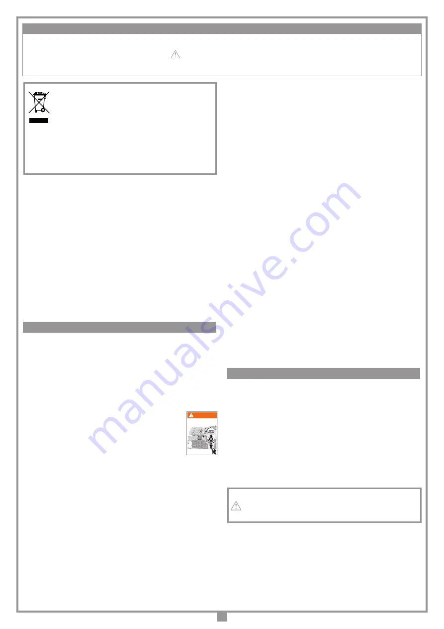
5)  At least two warning signs (similar to the example on the right) should 

be placed, where they can be easily seen by the public, in the area of 

the system of automatic operation. One inside the property and one 

on the public side of the installation. These signs must be indelible 

and not hidden by any objects (such as tree branches, decorative 

fencing etc.).

6)  Make sure that the end-user is aware that children and/or pets must 

not be allowed to play within the area of a road barrier installation. 

  Do not allow children to play with fixed controls and keep remote controls away 

from them. This appliance can be used by children aged from 8 years and above 

and persons with reduced physical, sensory or mental capabilities or lack of experi-

ence and knowledge if they have been given supervision or instruction concerning 

use of the appliance in a safe way and understand the hazards involved.

7)  A correct earth connection is fundamental in order to guarantee the electrical safety 

of the machine.

9) Before installing make sure that the ambient temperature falls within the range 

indicated on the appliance's data plate.

9)  If you have any questions about the safety of the boom operating system, do not 

install the operator. Contact your dealer for technical assistance.

Have the appliance controlled and checked at regular intervals by specialised main-

tenance personnel:

Check

 to be carried out after the first 

200.000

 manoeuvres (or six months after 

the installation);

Periodically check the correct operation of all safety devices (photoelectric cells etc.). 

Frequently examine the installation for imbalance where applicable and signs of wear 

or damage to cables, springs and mounting. 

Eventual repair work or maintenance must be carried out by specialised personnel 

using original spare parts. The appliance is not suitable for continuous operation 

and must be adjusted according to the model (see technical data on page 48).

TECHNICAL DESCRIPTION
ELDOM6DG

Automation for 6 m booms with a 

24 Vdc

 motor. 

Barrier cabinet with key lock, complete with boom support and LED flashing light 

built into the head of the structure plus mechanical release accessible with key 

from the outside

The incorporated electronic programmer contains the power stage, the logic control, 

the battery charger and the radio receiver module. The power supply is routed to the 

electronics card via a separate transformer which is housed in the same container.

DOM6 

Extruded aluminium boom with paint finish, 

6 metres long

, complete with PVC 

profiles.       

DOM6L 

Extruded aluminium boom with paint finish, 

6 metres long

, complete with LED 

lights and PVC profiles.       

BOXDOM 

Accessory box with DIN rails and fixing plates

ELUFS1 

Fixed aluminium support fork

BASEDOM68

Ground fastening base

• 

24 Vdc 

motor with tempered steel never ending screws;

-  lockable flip-back upper hood in spray-painted aluminium  with built-in warning 

lights;

-  external manual release mechanism with key access;

-  irreversible second stage reduction unit with tempered steel gears and first 

stage reduction worm gear in highly reliable self-lubricating POM, mounted on 

a cast aluminium stator;

-  boom balancing spring;

-  lubrication using permanently fluid grease;

-  barrier cabinet made of spray-painted metal (cataphoresis passi powder 

spray painting)

The minimum controls which may be installed are OPEN-STOP-CLOSE, these 

controls must be installed in a location not accessible to children.

During the opening/closing manoeuvre check for correct operation and activate 

the emergency stop button in case of danger.

During blackouts the boom can be released and manually manoeuvred (see 

manual manoeuvre pag. 18). 
•  The ground must be stable enough to firmly hold the plinth and the anchor 

plates.

•  Where possible protect the barrier cabinet from accidental knocks by 

passing vehicles.

•  Work out the run of the cables according to the command and control 

devices fitted and make sure the system conforms to the local standard 

and regulations in force (see installation example fig. 1 pag. 2).

It is very important that the barrier be well fixed to the fastening base 
as the ground anchors could loosen throughout time due to movement 
and vibration and cause damage to the cabinet.

FITTING THE UNIT (fig. 3-3a)

Prepare a cement base with the base plate and anchors "

C

" (optional) embed-

ded. The cable passage pipe "

D

" and the four threaded bolts 

M12

 must 

protrude (

30 mm

) from the base plate. 

The base plate must be perfectly in square, its surface must be clean 

and the four threaded bolts must emerge perpendicularly.

Note:

 the cement base "

A

" should preferably protrude 

50 mm

 out of the 

ground in order to avoid water build up which could damage the appli-

ance. The size of the base plinth "

B

" will vary according to the characteristics 

of the ground.

 IMPORTANT SAFETY INSTRUCTION

 INSTALLATION INSTRUCTIONS

AUTOMATIC OPENING

KEEP CLEAR

CHILDREN OR PETS MUST NOT 

BE ALLOWED TO PLAY ON OR 

NEAR THE INSTALLATION

WARNING

Summary of Contents for ELDOM34DG

Page 1: ...ostruttrice la quale ne ha verificato la perfetta corrispondenza delle caratteristiche con quelle richieste dalla normativa vigente This product has been tried and tested in the manufacturer s laboratory who have verified that the product conforms in every aspect to the safety standards in force Ce produit a été testé et essayé dans les laboratoires du fabricant Pour l installer suivre attentiveme...

Page 2: ...CLATURE 1 Barrière 2 Sélecteur à clé 3 Cellule photoélectrique 4 Interrupteur omnipolaire ouverture des contacts min 3 mm 5 Senseur magnétique 6 Lisse standard 7 Programmateur 8 Clignoteur 9 Lyre de repos 10 Profil en caoutchouc ZEICHENERKLÄRUNG 1 Schranke 2 Schlüsselschalter 3 Lichtschranken 4 Allpoliger Schalter mit einem Kontaktenabstand von 3 mm 5 Induktionsschliefe 6 Standard Schlagbaum 7 Ste...

Page 3: ...ALLATION FIXATION DE LA LISSE À GAUCHE BEFESTIGUNG DES SCHLAGBAUMS AUF DER LINKEN SEITE FIJACIÓN DE LA BARRA A LA IZQUIERDA 4 30 30 30 F 30 BASEDOM6 Contropiastra di fissaggio opzionale Ground fastening base optional Contre plaque de fixation en option Befestigungs Grundplatte extra Contraplaca de fijación opcional 3 6 5 H G 231 Installazione a pavimento senza contropiastra Pavement installation w...

Page 4: ...4 INSTALLAZIONE ASTA A DESTRA RIGHT HAND BOOM INSTALLATION FIXATION DE LA LISSE À DROITE BEFESTIGUNG DES SCHLAGBAUMS AUF DER RECHTEN SEITE FIJACIÓN DE LA BARRA A LA DERECHA 5 C B A F G G E ...

Page 5: ...TENUMKEHR SCHRANKENÖFFNUNG INVERSIÓN DE LA APERTURA DEL ASTA 6a 6b 6c Installazione asta a sinistra Left hand boom installation Fixation de la lisse à gauche Befestigung des Schlagbaums auf der linken Seite Fijación de la barra a la izquierda A B C D B A C D 6d B D C 6e Installazione asta a destra Right hand boom installation Fixation de la lisse à droite Befestigung des Schlagbaums auf der rechte...

Page 6: ...CHÉMA DE MONTAGE DE LA LYRE DE REPOS MONTAGESCHEMA DER AUFLAGESTÜTZEN ESQUEMA DE MONTAJE DEL APOYO FIJO 7 508 6000 150 90 S 500 40 200 7a MANOVRA MANUALE MANUAL MANOEUVRE MANŒUVRE MANUELLE MANUELLE BETÄTIGUNG MANIOBRA MANUAL 8 80 x 80 910 S 8a 5 5 180 1 2 3 4 Det A Det B ...

Page 7: ...CANIQUE DE LA POSITION HORIZONTALE VERTICALE DE LA LISSE MECHANISCHE EINSTELLUNG DER WAAGERECHTEN SENKRECHTEN SCHLAGBAUMSTELLUNG REGULACIÓN MECÁNICA DE LA POSICIÓN HORIZONTAL VERTICAL DEL BARRA 1 3 OK 2 4 5 6 10a 1 2 3 4 5 ACCESSO AL MOBILETTO ACCESS TO THE CABINET ACCÉDER À L ARMOIRE ZUGANG ZU DEM SCHRANK ACCESO AL GABINETE 30 40 3 1 4 2 10b 10 9 ...

Page 8: ...arillo Wh Bianco White Blanc Weiß Blanco Collegamenti scheda base CC ELXDOM24 CCi924 17 07 15 DI0552 Description Product Code Date Drawing number P J Heath CARDIN ELETTRONICA S p A 31020 San Vendemiano TV Italy via Raffaello 36 Tel 0438 401818 Fax 0438 401831 Draft CENTRALINA 1 MOTORE CC CON ENCODER CTRL 24Vdc CMN CMN TC2 N O CMN TA2 N O TC1 N O LP LED OUT 24Vdc 12 13 14 15 16 17 18 19 20 21 22 23...

Page 9: ...stributore del prodotto È buona norma far eseguire ad intervalli di tempo prestabiliti degli interventi di controllo e revisione dell apparecchiatura da parte di personale specializzato controllo dopo le prime 200 000 manovre o i primi 6 mesi dopo l installazione Verificare periodicamente il funzionamento delle sicurezze fotocellule ecc Esaminare periodicamente l impianto per verificare la presenz...

Page 10: ...STALLAZIONE ASTA fig 4 Inserire i connettori costa sensibile A nella staffetta C Con asta led inserire anche i connettori B Inserire l asta D e bloccarla utilizzando le sei viti e rondelle E Applicare il comprimozzo F fissandolo con le viti G INVERSIONE APERTURA ASTA fig 6 Per invertire il senso d apertura asta da sinistra fig 6a a destra fig 6e sbloccare l asta e portarla in posizione verticale A...

Page 11: ...P1 Tasto di navigazione sul menu P2 Tasto di programmazione e conferma PROG OK P3 Tasto di navigazione sul menu R1 Modulo RF 433 MHz per trasmettitore S4XX S500 32 CMN comune per i pulsanti di emergenza 33 EMRG1 N A ingresso pulsante per manovra di emergenza 1 34 EMRG2 N A ingresso pulsante per manovra di emergenza 2 TUTTI I CONTATTI N C NON UTILIZZATI VANNO PONTICELLATI Diconseguenzaitestsullesic...

Page 12: ... max 63 REG CONTRASTO SEC 26 PRELAMPEGGIO ON OFF LAMPEGGIANTE FISSO INTERMITTENTE LUCI ASTA FISSA INTERMITTENTE PROG OK per cambiare il valore RESET PARAMETRI OK VERSIONE FW ELDOM24 V0 04 USCITA PROG OK per ritornare al menu moto SELEZIONE MOTORE ELDOM24 3 4M 6M SENSORE CORRENTE LIVELLO 1 5 FRENATA IN CH SETTAGGIO 1 9 SELEZIONE MOTORE ELDOM24 3 4M 6M SENSORE CORRENTE LIVELLO 1 5 FRENATA CH SETTAGG...

Page 13: ...icurezze con contatto 8 2k cambiare l impostazione al menu sicurezze Prima di procedere alla programmazione della corsa dell asta impostare il motore corretto alla voce selezione motore del menu MOTO 5 Aux1 Aux2 chiusa aperta aux 1 segnale barriera chiusa aux 2 segnale barriera aperta ch2 luce di cortesia aux1 abilita il secondo canale dalla radio aux 2 contatto per la luce di cortesia chiusa luce...

Page 14: ...ul display È necessario entrare in modalità di programmazione per programmare il sistema Segnala che verrà eseguita la procedura di riposizionamento automatico In questo caso qualsiasi comando ricevuto TA TC o TD da inizio immediatamente a questa procedura Si verifica quando viene attivata una sicurezza FI FS CP durante la programmazione encoder o riposizionamento automatico Una volta ristabilito ...

Page 15: ... 31020 San Vendemiano TV Italy via Raffaello 36 Tel 0438 401818 Fax 0438 401831 Draft All rights reserved Unauthorised copying or use of the information contained in this document is punishable by law MR MODALITÀ DI FUNZIONAMENTO secondo dopodiché il ricevitore sarà pronto a memorizzare un altro codice 4 Per uscire dalla modalità lasciare trascorrere 3 sec senza memorizzare codici Il ricevitore em...

Page 16: ... soltanto in condizioni di estrema necessità Dopo aver effettuato una manovra di emergenza il programmatore elettronico perde la posizione dell asta fuori pos sul display e quindi al ripristino del normale funzionamento verrà effettuato il riposizionamento automatico LUCE DI CORTESIA USCITA CH2 RADIO STATO ASTA AUX1 AUX2 I morsetti 10 11 12 13 forniscono solamente un contatto puro e non danno una ...

Page 17: ...ersonswithreducedphysical sensoryormentalcapabilitiesorlackofexperi ence and knowledge if they have been given supervision or instruction concerning use of the appliance in a safe way and understand the hazards involved 7 Acorrectearthconnectionisfundamentalinordertoguaranteetheelectricalsafety of the machine 9 Before installing make sure that the ambient temperature falls within the range indicat...

Page 18: ...tion 5 tighten the nut 6 MECHANICAL ADJUSTMENT OF THE VERTICAL POSITION OF THE BOOM fig 10a Release the boom andraise it until the barrier is in the open position 1 Loosen the nut 2 by turning it counter clockwise put the spirit level 3 on the boom and turn screw 4 to adjust the vertical position With the boom in the correct position 5 tighten the nut 6 BALANCING THE BOOM fig 10b Release the boom ...

Page 19: ...e P1 Menu navigation button P2 Programming and confirm button PROG OK P3 Menu navigation button R1 Radio frequency module 433 MHz for series S4XX and S500 transmitters 32 CMN common for the emergency buttons 33 EMRG1 N A ingresso pulsante per manovra di emergenza 1 34 EMRG2 N A ingresso pulsante per manovra di emergenza 2 ALLUNUSEDNCCONTACTSMUSTBEJUMPEDandconsequentlythecorrespond ing security dev...

Page 20: ...e the value PROG OK to change the value PROG OK to change the value PROG OK to change the value PROG OK to change the value PROG OK to change the value PROG OK to change the value PROG OK to change the value CONTACT TB NC 8K2 CONTACT FI NC 8K2 CONTACT FS NC 8K2 CONTACT TB NC 8K2 CONTACT FI NC 8K2 CONTACT FS NC 8K2 PROG OK to confirm PROG OK to change the value PROG OK to change the value CONTACT T...

Page 21: ...s select the correct motor in the Motion menu 5 Aux1 Aux2 closed open aux 1 closed barrier signal aux 2 open barrier signal ch2 courtesy light aux 1 enables the second channel by radio aux 2 contact for courtesy light closed courtesy light aux 1 closed barrier signal aux 2 courtesy light 6 Setting the current sensor Level 1 motor input 2 amps Level 2 motor input 3 amps Level 3 motor input 4 amps L...

Page 22: ...C 00 000 007 07 06 13 15 35 PAUSA 030 Flashing on the display You have to enter the programming mode to program the system During normal operation it indicates that the automatic repositioning procedure is about to take place In this case any commands received TA TC or TD will automatically start this procedure This happens when an N C contact is activated FI FS CP during encoder programming or au...

Page 23: ...aft All rights reserved Unauthorised copying or use of the information contained in this document is punishable by law MR 4 To leave the programming mode wait for 3 seconds without pressing any buttons The receiver will sound a five second long beep and will then exit the program ming mode Note When the memory is entirely occupied the buzzer will sound 10 rapid beeps and will automatically leave t...

Page 24: ...ositioning manoeuvre COURTESY LIGHT CH2 RADIO OUTPUT BOOM STATUS AUX1 AUX2 Binding posts 10 11 12 13 only give a potential free contact this means that the courtesy light will have to be powered by an external circuit and the contact used as a simple switch The binding posts are linked to an NO contact relay the function of which can be activated through the men indicating the status of the barrie...

Page 25: ...rité de l installation interrompre la pose et contacter le distributeur du matériel Il est conseillé de faire contrôler et réviser l appareil selon les cadences préétablies par un personnel spécialisé Il est conseillé de faire contrôler et réviser l appareil selon les cadences préétablies par un personnel spécialisé contrôle après les premières 200 000 manœuvres ou 6 mois après l installation ATTE...

Page 26: ... la placer en contact avec la butée en ouverture 1 Desserrer l écrou 2 en le tournant dans le sens contraire aux aiguilles d une montre poser un niveau à bulle 3 sur la lisse et intervenir sur la vis 4 jusqu à ce que la lisse se trouve en position verticale Une fois que la verticale a été réglée 5 serrer l écrou 6 à fond N L All rights reserved Unauthorised copying or use of the information contai...

Page 27: ... la lisse Mettre sous tension le circuit et vérifier si l état des LEDs est conforme aux indications suivantes L1 Mise sous tension de la carte allumée L2 Défaut de connexion de la batterie éteinte 3 Signalisations sur le display en veille activé S1 Signalisation touche de blocage TB 4 TB S2 Signalisation cellules photoélectriques d inversion FI 4 FI S3 Signalisation cellules photoélectriques de s...

Page 28: ...pour changer la valeur SELECTION MOTEUR ELDOM24 3 4M 6M SENSEUR COURANT NIVEAU 1 5 FRENAGE EN FERMETURE RÉGLAGE 1 9 SELECTION MOTEUR ELDOM24 3 4M 6M SENSEUR COURANT NIVEAU 1 5 FRENAGE EN FERMETURE RÉGLAGE 1 9 PROG OK pour changer la valeur SENSEUR COURANT NIVEAU 1 5 FRENAGE EN FERMETURE RÉGLAGE 1 9 RALENT EN FERMETURE RÉGLAGE 1 9 PROG OK pour changer la valeur PROG OK pour changer la valeur Note 6...

Page 29: ... impérativement S il y a des dispositifs de sécurité avec contact 8 2k modifier le réglage dans le menu Sécurités Avant de lancer la programmation de la course de la lisse programmer le moteur à la rubrique sélection moteur du menu MOUVEMENT 5 Aux1 Aux2 fermée ouverte aux 1 signalisation de barrière fermée aux 2 signalisation de barrière ouverte ch2 éclairage de zone aux 1 valide le deuxième canal...

Page 30: ...icheur Il est nécessaire d entrer en programmation pour programmer le système Signale qu un repositionnement automatique sera effectué Dans ce cas une quelconque commande TA TC ou TD lance immédiatement ce procédé Ceci se produit si un dispositif de sécurité FI FS CP s active pendant la programmation de l encodeur ou le repositionnement automatique Une fois que les dispositifs de sécurité revienne...

Page 31: ... Fax 0438 401831 Draft All rights reserved Unauthorised copying or use of the information contained in this document is punishable by law MR MODES DE FONCTIONNEMENT COMMANDE PAR RADIO 3 Appuyer sur la touche de canal choisie précédemment sur l émetteur à mémoriser Le récepteur signalera que la mémorisation a eu lieu en émettant 2 bips d une demi seconde Après quoi le récepteur sera prêt à mémorise...

Page 32: ...rie usée ne doit pas être jetée dans les ordures ménagères mais il faut l éliminer dans le respect des normes en vigueur Dèsrétablissementdelatensionduréseaud alimentation letoutreprendraàfonctionner normalement pour pouvoir réutiliser la batterie il faudra qu elle se recharge La charge d une batterie efficiente peut durer au maximum 16 heures si le temps de charge est supérieur il vaut mieux la r...

Page 33: ...r Apparatur in festgelegten Zeitabständen vom Fachpersonal ausführen zu lassen Überprüfung nach den ersten 200 000 Betätigungen oder 6 Monate nach der Installation In regelmäßigen Abständen den Betrieb der Sicherheitsvorrichtungen Lichtschranken Sicherheitsleiste usw prüfen Die Anlage in regelmäßigen Abständen auf das Vorhandensein von Anzeichen eines Ungleichgewichts und von mechanischem Verschle...

Page 34: ...tgelieferten Unterlegescheiben befestigen Die Schrankenbasis kann auch auf einer schon bestehenden Betonfläche ange bracht werden wenn diese eine gute Qualität hat und deren Bodenstärke einen guten Halt des Dübels gewährleistet Empfohlener Dübel Stahlanker M12 Ø20 für Schwerbelastung SCHLAGBAUM MONTAGE Abb 4 DieSteckverbinderderSicherheitsleiste A indemVerbindungsstück C einsetzen Mit dem LED Schl...

Page 35: ...tigung PROG OK P3 Taste für Menünavigation R1 RF Modul 433 MHz für Sender S4XX oder S500 32 CMN Neutralleiter für Notbetätigungstasten 33 EMRG1 N O Kontakt Eingang Notbetätigungstaste 1 34 EMRG2 N O Kontakt Eingang Notbetätigungstaste 2 ALLE NICHT VERWENDETEN N C KONTAKTE MÜSSEN ÜBERBRÜCKT und somit auchdieTestsderentsprechendenSicherheitsvorrichtungen FI FS ausgeschaltetwerden WenndieTestsfürFI F...

Page 36: ... OK um den Wert zu ändern Anmerkung 6 Anmerkung 8 07 06 13 15 35 MOTORAUSWAHL ELDOM24 3 4M 6M STROMSENSOR NIVEAU 1 5 ABBREMSEN BEI SCHLIESSUNG EINSTELLUNG 1 9 PARAMETER RESET OK VERSION FW ELDOM24 V0 04 AUSGANG PROG OK Rückkehr zum Menü Bewegung PROG OK um den Wert zu ändern ABSTAND ÖFFNEN SCHRITTE 1 9 SCHLIESSGESCHWIND NIVEAU 1 3 PAUSENZEIT 130 SEK SCHLIESSGESCHWIND NIVEAU 1 3 PAUSENZEIT 130 SEK ...

Page 37: ...herheitsvorrichtungen zu ändern Vor der Programmierung des Schlagbaums ist der richtige Motor unter der Position Motorauswahl des Menüs Bewegung auszuwählen 13 Funktionen der Kanäle JederKanalderFunksteuerung A B C D kann konfiguriertwerden wobeiaus 7 verfügbaren Funktionen ausgewählt werden kann TD dynamische Taste TA Öffnung TC Schließung Blockierung CH2 Ausgang zweiter Kanal Ereignisse ein auf ...

Page 38: ... Systems sich in den Programmiermodus begeben Zeigt an dass die automatische Rückstellung ausgeführt wird In diesem Fall gibt jeder eintreffende Befehl TA TC oder TD zur sofortigen Ausführung dieses Vorganges Anlass Dieser Zustand tritt ein wenn ein Ausschaltgliedkontakt FI FS CP während der Encoderprogrammierung oder automatischen Rückstellung aktiviert wird Nachdem der passive Zustand der Sicher...

Page 39: ...r P J Heath CARDIN ELETTRONICA S p A 31020 San Vendemiano TV Italy via Raffaello 36 Tel 0438 401818 Fax 0438 401831 Draft All rights reserved Unauthorised copying or use of the information contained in this document is punishable by law MR 3 DievorabaufdemzuspeicherndenSendergewählteKanaltastedrücken Beierfolgter Speicherung gibt der Empfänger 2 eine halbe Sekunde lang dauernde Bip Töne von sich D...

Page 40: ... Die Eingänge EMRG1 und EMRG2 schließen die Logik aus und haben somit einen direkten Einfluss auf die Kontrolle des Motors Die Bewegung des Schlagbaums erfolgt auf Nenngeschwindigkeit und die Richtung der Bewegung hängt ab von der Installationsposition des Getriebemotors bei links installiertem Getriebemotor schließt EMRG1 und EMRG2 öffnet bei rechts installiertem Getriebemotor öffnet EMRG1 und EM...

Page 41: ... por parte de personal especializado control tras las primeras 200 000 maniobras o tras los primeros seis meses después de haberlo instalado Comprobar periódicamente el funcionamiento de los dispositivos de seguridad fotocélulas protector sensible etc Examinar periódicamente el equipo para verificar la existencia de desequilibrios y marcas provocadas por el desgaste mecánico daños de los cables mu...

Page 42: ...para sujetar las grapas e introducir la base C de la barrera Luego fijarla por medio de las cuatro tuercas de seguridad G y las arandelas correspondientes suministradas También es posible fijar la base de la barrera en un pavimento de cemento ya existente con tal que el grosor del pavimento sea tal que garantice el agarre del taco y esté hecha debidamente Taco aconsejado De anclaje en acero M12 Ø2...

Page 43: ...de RF 433 MHz para emisor S4XX S500 32 CMN común para las teclas de emergencia 33 EMRG1 N A entrada tecla para maniobra de emergencia 1 33 EMRG2 N A entrada tecla para maniobra de emergencia 2 TODOS LOS CONTACTOS N C QUE NO SE UTILICEN DEBEN PUENTEARSE y en consecuencia deben deshabilitarse los test en los dispositivos de seguridad corres pondientes FI y FS Si se habilita el test en FI y FS tanto ...

Page 44: ...ta 2 PRERRELAMPAGUEO ON OFF LUZ TESTIGO FIJA INTERMITENTE LUCES EN BARRA FIJA INTERMITENTE PROG OK para cambiar el valor Nota 1 SELECCIÓN MOTOR ELDOM24 3 4M 6M SENSOR CORRIENTE NIVEL 1 5 FRENADA EN CIERRE REGULACION 1 9 SELECCIÓN MOTOR ELDOM24 3 4M 6M SENSOR CORRIENTE NIVEL 1 5 FRENADA EN CIERRE REGULACION 1 9 PROG OK para cambiar el valor SENSOR CORRIENTE NIVEL 1 5 FRENADA EN CIERRE REGULACION 1 ...

Page 45: ... Antes de efectuar la programación de la carrera de la barra configurar el motor correcto en la posición selección motor del menú MARCHA 12 Funciones de los canales Cadacanaldelradiomando A B C D puede configurarseseleccionando e n t re 6 f u n c i o n e s disponibles TD tecla dinámica TA apertura TC cierre Bloqueo CH2 salida segundo canal de radio eventos On Off 5 Aux1 Aux2 cerrado abierto aux 1 ...

Page 46: ...espondiente apagado cuando un obstáculo se encuentra en el medio del radio de acción de los mismos Si se detectara una anomalía cambiar el dispositivo de seguridad en avería o puentear la respectiva entrada e inhabilitar el test correspondiente al dispositivo de seguridad mismo menu opciones Se presenta cuando el programador proporciona un mando al motor pero el motor no se pone en marcha Es sufic...

Page 47: ...thorised copying or use of the information contained in this document is punishable by law MR 3 Pulsar la tecla de canal anteriormente seleccionada en el emisor por memorizar tras haber realizado la memorización el receptor emitirá 2 bips de medio segundo y a continuación el receptor estará listo para memorizar otro código 4 Parasalirdelamodalidad esperar3segundossinmemorizarcódigos Elreceptor emi...

Page 48: ... cierra Atención Durante la maniobra de emergencia todos los dispositivos de seguridad resultan deshabilitados y no existe control alguno sobre la posición de la barra en consecuencia soltar las teclas antes de que llegue al tope Utilizar la maniobra de emergencia sólo en condiciones de máxima urgencia Tras haber efectuado una maniobra de emergencia el programador electrónico pierde la posición de...

Page 49: ...NOTES 49 ...

Page 50: ...NOTES 50 ...

Page 51: ...NOTES 51 ...

Page 52: ...ntation du moteur Vdc 24 Puissance maximum absorbée W 120 Courant nominal absorbé A 3 Récepteur incorporé Fréquence de réception MHz 433 92 486 3 Nombre de canaux Nbre 4 Nombre de fonctions disponibles Nbre 8 Nombre de codes mémorisables Nbre 300 1000 Stromversorgung Vac 230 Nennstrom A 0 9 Aufnahmeleistung W 250 Betriebsintermittenz 90 Versetzungsgeschwindigkeit m min 6 Öffnungszeit 90 s 5 7 Durc...

Reviews: